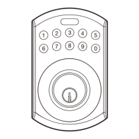
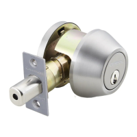
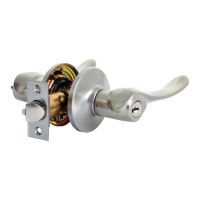
EasyManua.ls Logo

Garrison 046-5681-0 User Manual

Garrison 046-5681-0
8 pages
To Next Page IconTo Next Page
Page #1 background imageLoading...
Page #1 background image
HANDLESET
WITH ELECTRONIC DEADBOLT
Instruction Manual
model no. 46-5681/46-5682
Toll-free: 1-866-523-5218
IMPORTANT:
Please read this manual carefully
before installing this deadbolt lock and save it for reference
1
2
3
4
5
6
7
8
9
0
TEMPLATE
45 40 35
1 3/4" 1 9/16" 1 3/8"
Fold on dotted line and
fit on door edge
FOR 70 mm (2 3/4") BACKSET
FOR 60 mm (2 3/8") BACKSET
51
2"
Mark Ø1" (25.4 mm) hole at
center of door edge.
Ø2 1/8" (54 mm)
WO
Date
Artist
PROCESS
MAGENTA
PANTONE
287C
PROCESS
BLACK
PANTONE
000
PANTONE
000
PANTONE
000
11/08/13
01a
Brenda
638604 CTC Generic 815446 LITHO FLEXO
mm/dd/yy
02a
xxxxxx
mm/dd/yy
03a
xxxxxx
mm/dd/yy
04a
xxxxxx
mm/dd/yy
05a
xxxxxx
mm/dd/yy
06a
xxxxxx
mm/dd/yy
07a
xxxxxx
46_5681_46_5682
Limited Warranty Statements
1. Warranty
The manufacturer warrants the product to be free from
defects in material and workmanship for a period of
12 months from the original date of purchase. If you
discover a defect in the product covered by this warranty,
we will repair or replace the item at our option using new or
refurbished components.
2. Exclusions
This warranty covers defects in manufacturing discovered
while using the products as recommended by the manufacturer
rather than occurred by the act of God, and damages caused
by misuse, abuse, and unauthorized modification.
3. Limited Liability
The manufacturer will not be held liable for incidental or
consequential losses or damages to any act of God.
4. Reminder
Service requirement shall subject to the presentation of this
Warranty Card. The Warranty Card will not be reissued if lost.
Product: HANDLESET WITH ELECTRONIC DEADBOLT
Purchase Date:
02a
11/26/13
Brenda
02b
11/29/13
Brenda
046-5681-0 to 046-5681-8 & 046-7244-0 to 046-7246-6

Questions and Answers:

Garrison 046-5681-0 Specifications

General IconGeneral
BrandGarrison
Model046-5681-0
FinishSatin Nickel
HandingReversible
Strike Plate IncludedYes
Keyed AlikeNo
MaterialMetal
TypeEntry
Backset2-3/8 inches
Door Thickness1-3/8 inches to 1-3/4 inches
Latch Size1 inch
ANSI GradeGrade 3
Power SourceMechanical

Summary

Limited Warranty Statements

Installation Guide: Door Preparation

Door Template and Marking

Use template to mark door for hole placement and backset.

Drilling Door Holes

Drill holes for lockset and latch according to marks.

Latch Installation

Insert latch into door edge and secure with screws.

Strike Plate Installation

Install strike plate into door frame for latch alignment.

Installation Guide: Assembly Steps

Keypad Assembly Mounting

Mount keypad assembly onto the door with tailpiece inserted.

Interior Mounting Plate

Secure interior mounting plate to the door.

Door Handing Identification

Determine if the door is left-handed or right-handed.

Turn Piece Adjustment

Set turn piece orientation for door handing.

Receiver Module Installation

Connect IC wire and attach receiver module with batteries.

Deadbolt Component Overview

Programming Button Function

Button for codes, errors, and locking.

Number Buttons Function

Buttons for entering user codes.

Cylinder and Washer

Key operation, water prevention, and battery lid.

Reset and Turn-Piece

Reset button and interior locking mechanism.

Specifications and Functions: Part 1

Battery Requirements

Requires four AA 1.5V alkaline batteries.

Battery and Indicator Status

Low battery warning, LED, and audio indicators.

Programming Code Details

Default code is 0000; used for setting functions.

Specifications and Functions: Part 2

User Code Management

Managing user codes, including creation and deletion.

Temporary User Code Disablement

Deactivate user codes for key-only operation.

Disposable User Code Creation

Create a one-time use code.

Factory Reset Procedure

Reset to original settings using the 'R' button.

Lock and Unlock Operations

Methods to lock and unlock the deadbolt.

Door Closing and Latch Issues

Troubleshooting for latch and door alignment problems.

Auto-Locking Function

Set automatic door locking after a delay.

Mute Functionality

Control audible beeps for operations.

Specifications and Functions: Part 3

Code Protection and Illumination

System lock after errors and keypad light-up.

Function Programming Guide: Part 1

Door Handing Identification

Identify door handing before initial setup.

Adding and Deleting User Codes

Process to add and remove user codes.

Changing Programming Code

How to change the master programming code.

Auto-Locking Feature Control

Enable or disable the auto-locking feature.

Function Programming Guide: Part 2

Setting Autolock Time Delay

Set the delay time for auto-locking.

Toggling Mute On/Off

Turn audible beeps on or off.

User Code Enable/Disable

Activate or deactivate all user codes.

Creating Disposable User Codes

Create a one-time use code.

Restoring Factory Settings

Reset the lock to factory default settings.

Simple Troubleshooting: Part 1

Simple Troubleshooting: Part 2

User Code and Function Setup Tips

Ensure Door is Unlocked

Ensure door is unlocked during programming.

Perform Door Handing Identification

Identify door handing before setup.

Change Default Codes

Change default codes for security.

Understanding Indicator Feedback

Understand LED and beep codes for programming feedback.

Programming Step Timing

Complete each programming step within the time limit.

Lock/Unlock Method Overview

Overview of locking/unlocking methods.

Related product manuals