66481 / 02
Mark the Door with Template
Select the height and backset as desired on the
door face; use the TEMPLATE as an indication to
mark the center of the circle on the door face and
the center of the door edge.
2
5 9
10
11
6
7
8
Install Strike
Machine Screws Qty. 3
Wood Screws Qty. 5
Deadbolt Chassis Screws Qty. 2
I
J
K
Adjust Thumb Turn Piece
Install Receiver Module
Insert Batteries
Install Keypad Assembly
Install Inside Mounting Plate
Identify Door Handing
To identify the center of strike, close
the door to lay the latchbolt against
the door frame.
Mark the center line on the doorframe
exactly opposite the latch hole in the
door edge.
Install cylinder into the deadbolt
keypad assembly with tailpiece in
horizontal position inserted through
hub of the latch.
the mounting plate.
Fix the mounting plate with screws.
If outside lock assembly is lopsided,
please loosen the screws to adjust its
position and tighten the screws again.
Pass the IC wire through the wire hole of
Face the door from the outside.
The door is left-handed if the hinges are on the left side of the door,
whereas the door is right-handed if the hinges are on the right side of the door.
the interior side of the door, and
insert the tailpiece through the
cross-shaped crank of the latch
Pass the IC wire under the latch to
.
Install the strike plate into your door
frame and tighten with wood screws.
c
Left-handed
Right-handed
Mounting Plate
Screws
Do not use an electric screwdriver during installation.
This Manufacturer advises that no lock can provide complete security by itself.
This lock may be defeated by forcible or technical means, or evaded by entry elsewhere on the property.
No lock can substitute for caution, awareness of your environment, and common sense.
Builder's hardware is available in multiple performance grades to suit the application.
In order to enhance security and reduce risk, you should consult a qualified locksmith or other security professional.
Backset is a distance from door edge to center of
hole on door face.
Adjustable latch fits both backset of 2-3/8 in.
(60 mm) and 2-3/4 in. (70 mm).
Backset Determination
1
Drill Holes
Using the marks as a guide, drill a hole
Ø2-1/8 in. (54 mm) through the door face for the
lockset, then a hole of Ø1 in. (25.4 mm) for latch.
3
Install Latch
Insert the latch and ensure it is parallel to the door face.
Mark the outline of the faceplate, then take out the latch.
You need to stay this
way up when inserting
the latch.
Make sure the cross in the latch is
on the bottom.
a
4
PACKAGE CONTENTS
HARDWARE SCREWS CONTENTS
2-3/4 in. (70 mm)
2-3/8 in. (60 mm)
Determine if the latch needs to be adjusted to the 2-3/4 in. (70 mm)
backset. To adjust, rotate the latch until it stops.
Reverse the direction to return to the 2-3/8 in. (60 mm) backset.
LATCH ADJUSTMENT
ELECTRONIC DEADBOLT
Installation Guide
Insert the latch into the door.
(Make sure the cross is on the bottom
of the latch.)
Use 2 wood screws to secure latch.
Please do not fully tighten the screws
until lock is completely installed.
Chisel 5/32 in. (4 mm) deep along
the outline to allow the faceplate to
be aligned with the door edge.
b
Measure one half of door thickness
from door stop and vertically mark
center line of strike.
Drill 1 in. (25.4 mm) hole, 1 in.
(25.4 mm) deep at intersection of
horizontal and vertical line of strike.
Chisel 5/64 in. (2 mm) deep along
the strike outline to allow the strike to
be aligned with the door frame.
Rotate the thumb turn piece to the LEFT
at 45 degrees for right-handed doors.
Rotate the thumb turn piece to the RIGHT
at 45 degrees for left-handed doors.
To remove battery cover, first push
up on the cover, then pull out.
Battery Cover
Screws
Wood Screw
Connect the IC wire into the back of
the receiver module.
Ensure that the deadbolt tailpiece is
engaged with turn piece, then attach
receiver module to the door with
screw.
Use the optional wood screw to
secure the receiver module to wood
doors only.
Insert 4 (AA) 1.5 V alkaline batteries (not included) and slide the battery cover
back onto the receiver module.
Remarks:
(1) Alkaline batteries are recommended in order
to stabilize the power supply.
Using batteries other than alkaline will greatly
reduce performance.
(2) All settings will be retained in the memory
even if the batteries go completely dead.
TEMPLATE
45mm 40mm 35mm
1-3/4 in. 1-9/16 in. 1-3/8 in.
Fit here on door edge
FOR BACKSET 2-3/4 in. (70 mm)
FOR BACKSET 2-3/8 in. (60 mm)
51mm
2 in.
Mark Ø1 in. (25.4 mm) hole
at center of door edge.
Ø2-1/8 in. (54 mm)
For right-handed
door
For left-handed
door
a
180°
70 mm
60 mm
b
c
Hinge Hinge
Cylinder
IC wire
B
Description
Quantity
Part
A
B
C
D
Key
Cylinder
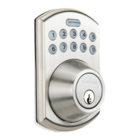
Deadbolt Keypad Assembly
Deadbolt Latch
2
1
1
1
E
F
Strike Plate
Mounting Plate
1
1
Part
Description
Quantity
G
H
Receiver Assembly
Battery Cover
1
1
H
I
G
K
F
E
J
D
C
A
Tailpiece must be
horizontal!
FEDERAL COMMUNICATIONS COMMISSION STATEMENT
This device complies with Part 15 of the FCC. Operation is subject to the following two conditions: (1) this device may not cause harmful interference, and (2) this device must accept any interference
received, including interference that may cause undesired operation. Changes or modications not expressly approved by the party responsible for compliance could void the user‘s authority to operate the
equipment. NOTE: This equipment has been tested and found to comply with the limits for a Class B digital device, pursuant to part 15 of the FCC Rules. These limits are designed to provide reasonable
protection against harmful interference in a residential installation. This equipment generates, uses and can radiate radio frequency energy and, if not installed and used in accordance with the instructions,
may cause harmful interference to radio communications. However, there is no guarantee that interference will not occur in a particular installation. If this equipment does cause harmful interference
to radio or television reception, which can be determined by turning the equipment off and on, the user is encouraged to try to correct the interference by one or more of the following measures:
—Reorient or relocate the receiving antenna.
—Increase the separation between the equipment and receiver. —Connect the equipment into an outlet on a circuit different from that to which the receiver is connected.
—Consult the dealer or an experienced radio/TV technician for help.
WARRANTY
The retailer of this product hereby warrants, subject to the conditions set forth below, that it will either repair or replace, at its option, this product if it proves to be defective by reason of improper workmanship
or materials within the original purchaser’s limited time. In order to obtain repairs or replacement under this limited warranty you must bring this product to the retailer’s store in which you bought it. Original
purchaser: This limited warranty is limited to the original purchaser at retail of this product from retailer. Limited 25 years mechanical and 1 year electronic warranty. Except to the extent prohibited by applicable
law, no other warranties, whether express or implied, including the warranties of merchantability and tness for a particular purpose, shall apply to this product. Under no circumstances shall retailer be liable for
consequential or incidental damages in connection with this product. To the extent retailer is prohibited by applicable law from excluding implied warranties, the duration of such implied warranties which are not
excludable shall be the original purchaser’s limited warranty time. Some states do not allow the limitation on how long an implied warranty lasts, so the above limitation on the duration of implied warranties which
are not excludable, if any, may not apply to you. Some states do not allow the exclusion or limitation of incidental or consequential damages, so the above limitation or exclusion of incidental or consequential
damages may not apply to you. Retailer neither assumes nor authorizes any representative or other person to assume for it any obligation or liability other than such as is expressly set forth herein. This limited
warranty gives you specic legal rights, and you may also have other rights which vary from state to state. For warranty service, please call 1-877-442-8347, 8:00 a.m. - 8:00 p.m., EST, Monday - Friday.
SAFETY INFORMATION
Read the precautions and instructions in this manual before installing and
using this lock. Save this manual for future reference.
WARNING: Do not use an electric screwdriver during installation.
CAUTION : Please use four alkaline batteries (not included) for best performance.
A. Do not attempt to disassemble any internal components of the lockset. Doing so will void the limited warranty.
B. Do not drop or hit the lockset. Too much shock may result in permanent damage.
C. Do not use pins or sharp objects to press the keypad.
D. Always create a backup of information you wish to keep (Programming Code, user code, etc.).
E. Promptly change the Programming Code before operating this lockset.
WARNING: The Manufacturer advises that no lock can provide complete security by itself. This
lock may be defeated by forcible or technical means, or evaded by entry elsewhere on the property.
No lock can substitute for caution, awareness of your environment, and common sense. Builder’s
hardware is available in multiple performance grades to suit the application. In order to enhance
security and reduce risk, you should consult a qualied locksmith or other security professional.
Replacement Parts List & Troubleshooting
For replacement parts & troubleshooting, call customer service at
1-877-442-8347, 8:00 a.m. - 8:00 p.m., EST, Monday - Friday. AB16649
Item #0817538
ELECTRONIC KEYPAD DEADBOLT
Model #G2X2D01
Questions
Call customer service at 1-877-442-8347,
8:00 a.m. - 8:00 p.m., EST, Monday - Friday.
ATTACH YOUR RECEIPT HERE
Serial Number
Purchase Date
PREPARATION
Before beginning installation of product, make
sure all parts are present. Compare parts with
package contents list and hardware contents
list. If any part is missing or damaged, do not
attempt to assemble, install or operate the product.
Contact customer service for replacement parts.
ESTIMATED ASSEMBLY TIME: 40 - 60 MINUTES
CARE AND MAINTENANCE
THE FOLLOWING CARE INSTRUCTIONS SHOULD BE FOLLOWED TO ENSURE A LONG LASTING FINISH:
1. Remove locks, or do not install locks, prior to painting your door.
2. Do not use any chemical liquid or lubricating oils with additives to clean the lock.
PACKAGE CONTENTS
HARDWARE CONTENTS
• Pencil
• Chisel
• 1 in. (25.4 mm) and
1/8 in. (3 mm) Drill Bits
• Tape Measure
• Hammer
• Phillips Screwdriver
• Power Drill
• 2 in. (51 mm) 6d
Common Nail
• 2-1/8 in. (54 mm) Hole
Boring Bit
TOOLS NEEDED FOR NEW INSTALLATION:
(NOT INCLUDED)
B
Description
Quantity
Part
A
B
C
D
Key
Cylinder
Deadbolt Keypad Assembly
Deadbolt Latch
2
1
1
1
E
F
Strike Plate
Mounting Plate
1
1
Part
Description
Quantity
G
H
Receiver Assembly
Battery Cover
1
1
H
I
G
K
F
E
J
D
C
A
TEMPLATE
1-3/4 in.
45 mm
1-9/16 in.
40 mm
1-3/8 in.
35 mm
Fit here on door edge
2 in.
51 mm
Mark Ø1 in. (25.4 mm) hole
at center of door edge.
Ø2-1/8 in. (54 mm)
FOR BACKSET 2-3/8 in. (60 mm)
FOR BACKSET 2-3/4 in. (70 mm)
27/32 in. (21.5 mm)
Mounting Screws, Qty. 3
2-43/64 in. (68 mm)
Mounting Screws, Qty. 2
3/4 in. (19 mm)
Wood Screws, Qty. 5
I
J
K
Printed in Taiwan