02. Installation
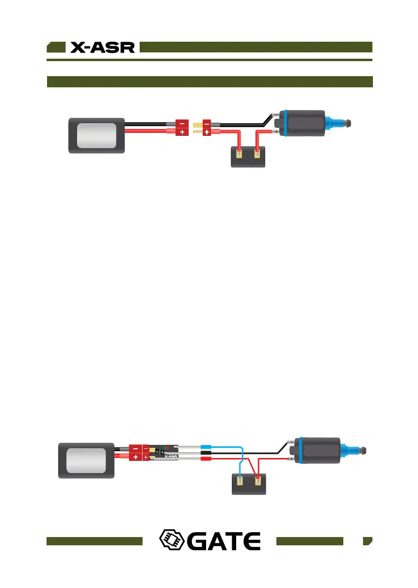
Fig 1. Standard AEG wiring scheme
BATTERY
UP TO 12.8V
AEG Motor
A B
CONTACTS
C
To adapt the standard AEG installation to work with X-ASR it is necessary to get to
the trigger contacts. In case of GB v2 contacts are located inside a gearbox. With a
version 3 gearbox, the installation will be easier because the contacts are outside of
the gearbox. Please consult a local airsoft technician if you have never
disassembled a gearbox before or if you have any installation concerns.
a) Installation of X-ASR without replacement of wires. Using this method, the
original wiring is kept intact, and the connections are modified. Referencing
Fig 1., de-solder A wire from the one of the trigger contacts and then solder it to the
B wire. It does not matter which wire you disconnect from the trigger switches, just
join the two wires together at one terminal. In the place of the A wire, solder the
additional single signal wire. The trigger wire can be very thin because it handles
very low current and it is only used for switch-detection.
USER GUIDE
1.
AEG Motor
CONTACTS
BATTERY
UP TO 12.8V
07
WWW.GATEE.EU