Do you have a question about the GAUGEMASTER PRODIGY ADVANCE and is the answer not in the manual?
How to connect the DCC system and power supply to the decoder for operation.
Guidance on using LED's and slow motion point motors with decoder output pairs.
Explains the Control Variables (CVs) and their mapping for decoder configuration.
Instructions for programming the main address (CV513) of the accessory decoder.
How to set output modes for pairs A, B, C, and D using specific CVs.
Procedure for connecting the decoder to twin coil point motors.
Modifying the decoder for twin coil point motors by cutting the red wire.
How to program decoder CVs on the main track using OPS mode.
Steps to operate the decoder using the Prodigy Advance controller interface.
Setting individual delays for outputs for cascading or route effects.
Guidance on setting up routes with accessories using the DCC system.
Details regarding warranty, customer support, and repair procedures.
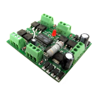
The PRODIGY ADVANCE DCC30 Stationary Accessory Decoder is an NMRA-compatible accessory decoder designed to control various accessories on a model railway layout. It functions as four decoders in one, each with its own sub-address, allowing for versatile control of multiple accessories. The decoder can be powered either directly from the DCC track rails or by an external 16V AC power supply, with the latter being recommended to preserve the DCC system's power for running trains. A key feature is its ability to rectify AC power, eliminating the need for separate DC power supplies for accessories like slow-motion DC point motors or LEDs.
The decoder provides four pairs of outputs, labeled A, B, C, and D, each corresponding to a sub-decoder. Each sub-decoder has three terminal connectors: OUTPUT 1, COMMON, and OUTPUT 2, which connect directly to the accessory or point motor. The main address of the decoder (CV513) is pre-programmed to #1 at the factory, with sub-addresses 1, 2, 3, and 4 automatically assigned to outputs A, B, C, and D, respectively. For additional decoders, their main addresses can be programmed to #5, #9, #13, and so on, with subsequent sub-addresses following suit.
The output mode for each pair of outputs (CV515 for Pair A, CV516 for Pair B, CV517 for Pair C, and CV518 for Pair D) can be set to one of three types:
The decoder also supports a programmable time delay for each output (CV563 for output A, CV564 for output B, CV565 for output C, and CV566 for output D). This delay, ranging from 0.1 to 3 seconds (values 1 to 30), is useful for creating cascading effects in route settings.
Connecting the decoder involves either running two wires from the DCC unit or track rails to the lower two input terminals ("from DCC track") and connecting an external 16V AC power supply to the upper two input terminals ("16v AC INPUT"), or, if using DCC signal to power accessories, jumping the lower two input terminals to the upper two. The latter method, however, will reduce the power available for operating trains.
For slow-motion DC point motors or signal LEDs, the decoder's rectified DC output can be used directly. Ten 300-ohm resistors are included for use with these accessories. When connecting twin-coil AC point motors, it is imperative to reprogram the decoder to the momentary ON/OFF mode before connection to avoid burning out the motors. If the decoder is exclusively used for twin-coil point motors, a red wire on the board can be cut to automatically set the decoder for this type of motor.
Programming the decoder can be done on a program track using CV1 to CV6 as a mapping for CV513 to CV518, or on the main track (OPS mode programming) for CV515, CV516, CV517, and CV518, provided the main address is known. When setting routes, users should consult the PRODIGY ADVANCE User Manual. It is important to ensure that the power supply can handle the load when multiple accessories are activated simultaneously, especially with twin-coil point motors, as high current surges can trigger short-circuit protection in the DCC system.
The manual emphasizes the importance of correct programming, particularly for twin-coil point motors, to prevent damage to both the decoder and the motors. If a twin-coil motor is stiff or difficult to activate, the input value can be gradually increased from 1 to find the optimal setting, avoiding excessively high values that could cause overheating.
For technical support or if a decoder is believed to be faulty, users are advised to contact Gaugemaster by telephone in the first instance. If a return is necessary, the device should be sent via insured post and securely packed to the provided postal address. The PRODIGY ADVANCE user manual is available for download from the Gaugemaster website or can be obtained by sending a self-addressed envelope. The website also serves as a resource for additional technical information.
| Manufacturer | Gaugemaster |
|---|---|
| Type | DCC System |
| Programming Track Output | Yes |
| Display | LCD |
| Feedback | No |
| Computer Interface | No |
| System Components | Handheld controller, base station, power supply |
| Locomotive Control | DCC |
| Accessory Control | DCC |
| Consisting | Yes |
| Compatibility | DCC compatible systems |