This manual is from
http://groups.msn.com/UKSecurityPanels
www.thesecurityinstaller.co.uk
6. Wiring the Control Panel
a) Mains Connection
The mains supply to the control panel is connected via a 3 way terminal block located in
the bottom centre of the control panel. Mains should be supplied to the control panel via
a fused spur.
b) Battery Connection
The Rascal Super requires a 1.9AH battery to be fitted to provide power in the event of a
mains failure.
c) Detector Circuits
Connections are provided for up to five detector circuits. These connectors are for closed
circuit detection devices. A common tamper loop is required for all detection devices.
The circuits are located on the bottom LHS of the control board.
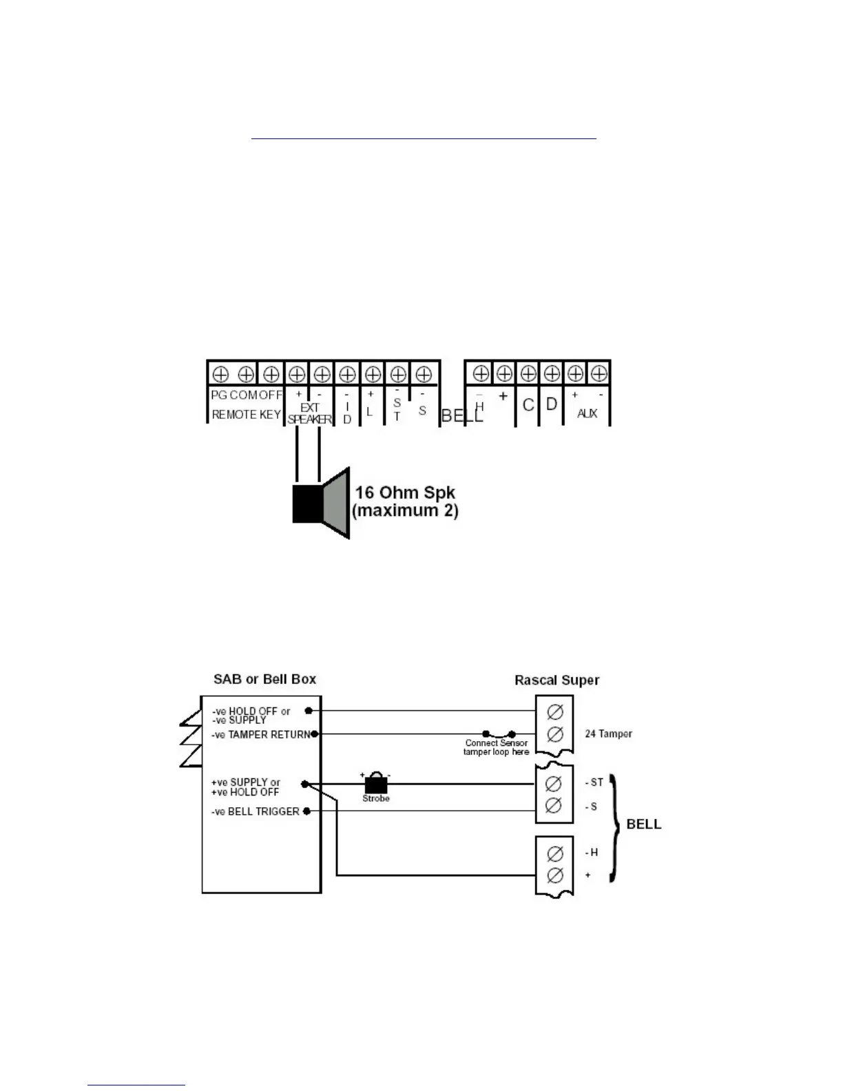
d) Internal Sounders
A connection is provided to allow internal extension speakers to be fitted . Up to two
16
Ω
extension speakers may be fitted to the system.
Note : To reduce the volume of the speakers cut the resistor (option 1) shown on the PCB
drawing.
e) External Sounder & Strobe
Connections for the external sounder and strobe are shown below. Note bell trigger
shown is with output programmed for applied negative (negative bell trigger).
(i) ST- Strobe switched negative
(ii) S- Bell switched negative trigger
(iii) H- Siren hold off (open circuit in alarm)
(iv) + Bell hold off supply
f) AUX DC Detector Power
Auxiliary power is provided from the connections at the bottom RHS of the main PCB and
the Bell+. These provide power for detectors and other devices requiring external power.
The auxiliary power output is rated at 500mA and 12V (nominal).
 Loading...