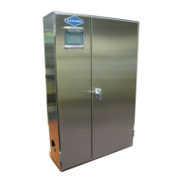
Do you have a question about the GAYLORD CG3 Series and is the answer not in the manual?
Explains the meaning of prefixes used in CG3 ventilator model numbers.
Explains the wash cycle activation, process, and duration for cleaning the ventilator.
Details the automatic internal fire protection mechanism activated by thermostats.
Explains how the External Fire Mode is activated by system microswitch or fire switch.
Instructions for starting the exhaust fan using the Command Center.
Details how to stop the exhaust fan and initiate the wash cycle.
Explains how the detergent pump draws and pushes detergent during the wash cycle.
Provides dilution instructions for Formula G-510 for normal and light-duty cleaning.
Step-by-step guide for manual operation of the Command Center.
Explains how to set up automatic fan and wash cycles using the time clock.
Details the functions and procedures for navigating the C-6000 Command Center menus.
Chart detailing designed CFM per lineal foot for various models and configurations.
Chart detailing optimum inlet slot velocities for CG3 series ventilators.
Step-by-step instructions for measuring inlet slot velocities.
Identifies causes and corrective actions for smoke loss from the ventilator.
Addresses poor grease extraction and potential causes like low exhaust volume.
Troubleshooting steps for exhaust fan not starting or operating correctly.
Further troubleshooting for inadequate wash time, clogged nozzles, and pump issues.
Troubleshooting for internal and external fire cycle activations and related issues.
Lists status lights on the PLC and their meaning for correct operation.
Table showing terminal voltages for different C-6000 control models.
Specifies the voltage for the C-6000-20-B wiring diagram.
Details the PLC input/output schedule for the C-6000-20-B.
Explains symbols and terms used in the wiring diagram.
Provides important general notes related to the wiring diagram.
Specifies the voltage for the C-6000-20-B wiring diagram.
Procedures for testing thermostat and remote fire switch functions.
 Loading...