Do you have a question about the GE Medical Systems Dash 3000 and is the answer not in the manual?
History of manual revisions and their dates.
Defines terms like DANGER, WARNING, CAUTION, and NOTE for hazard communication.
Lists requirements for equipment servicing and maintenance.
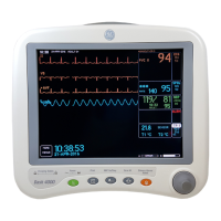
Describes the patient monitor and its network connectivity options.
Lists the available software packages for monitor configuration.
Lists key performance metrics for display and controls.
Identifies connectors on the back of the monitor for equipment and network.
Describes Ethernet as the main link for the Unity Network.
Lists recommended regular maintenance tasks for monitor functionality.
Routine inspection of the monitor's physical condition.
Lists approved cleaning solutions and agents to avoid.
Procedure for cleaning the monitor's print head.
Explains how the battery is charged when connected to AC power.
Explains the purpose of electrical safety tests.
Lists recommended equipment for checkout procedures.
Menu for downloading boot code or main code software.
Steps to access and navigate the Review Errors menu.
Details what error logs contain and their use in troubleshooting.
Lists conditions that trigger battery alarms.
Procedure to confirm AC power from the wall receptacle is correct.
Steps to test ECG signal acquisition and display.
Troubleshooting steps for network communications over Wireless LAN.
Guides on diagnosing problems based on symptoms and reasons.
Describes error messages and how to resolve them.
Lists information needed before configuring a monitor.
Lists options available in the monitor's main menu.
Configures the care unit name for network identification.
Sets the patient bed number for network identification.
Determines the type of monitor desired (adult, neonatal, OR).
Configures display locations for manual, alarm, and print graphs.
Verifies communication across the network.
Troubleshooting tips if the writer or printer does not graph.
Determines the function of the monitor (e.g., STANDARD, ROVER).
Configures the marker out signal for the DEFIB SYNC connector.
Configures the monitor line frequency to 50 or 60 Hz.
Sets the CIC and QS Protocol, default is Seg50/51.
Sets the MUSE Protocol to Hilltop or Seg50/51.
Menu option reserved for future use.
Selects a particular set of GE factory defaults.
Confirms the configuration of the optional Wireless LAN.
Changes the language of the displayed text.
Final step after configuration, proceed to checkout.
Procedures for advanced users only, should be used rarely.
Steps to store monitor default settings for transfer.
Assigns an identification number to each device on the Unity Network.
Procedure to review the error logs of a monitor.
How to view specific errors in the log.
Explains parameters found in sample error logs.
Lists common error codes and their descriptions.
Explains the severity levels of logged errors.
Procedure to copy and transfer error logs to a central station.
Steps to access the COPY LOGS menu on the central station.
Selects the device from which to copy logs.
Selects the date for which to retrieve error logs.
Initiates the process of copying error logs to a floppy diskette.
Option to eject the floppy diskette from the central station.
No field adjustments or calibration for hardware components.
Software calibration for NBP, Analog Output ECG, BP, and End-tidal CO2.
Prerequisites for ECG/BP calibration, including voltmeter connection.
Steps to calibrate the BP analog output.
Refers to the operator's manual for CO2 calibration.
Critical warnings regarding field repairs and battery hazards.
Guidelines to prevent ESD damage to components.
Reminds to complete calibration and safety tests after reassembly.
Table mapping FRU replacements to required tests.
Steps to remove the monitor handle assembly.
Procedure to replace or upgrade the alarm light.
Procedure to separate the display assembly from the main unit.
Procedure to replace the backlight inverter PCB.
Procedure to replace the key pad assembly.
Procedure to replace the LCD color display.
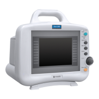
Procedure to replace or upgrade the Dash 4000 alarm light.
Procedure to replace the Dash 4000 front panel PCB.
Steps to remove DAS and NBP assemblies.
Steps for replacing writer, speaker, or upgrading RF LAN.
Steps for replacing processor/power management PCB and battery assembly.
Steps for replacing the power supply assembly.
Steps for replacing the speaker.
Steps for installing the RF LAN upgrade.
Procedure to confirm the Wireless LAN option is enabled.
Steps to verify the Wireless LAN ID.
Steps to verify wireless LAN communication.
Procedure to replace the optional printer.
Overview of the section's content: Theory of Operation, drawings, lists, and connections.
Lists the main components of the monitor assembly.
Technical diagram illustrating the electrical layout of the system.
Assembly diagram showing the physical arrangement of parts.
List of parts with item numbers and descriptions for PN 2004323.
Assembly diagram for the Dash 3000 display unit.
List of parts for the Dash 3000 display assembly.
Assembly diagram for the Dash 4000 display unit.
List of parts for the Dash 4000 display assembly.
Assembly diagram for the back panel of the Dash 3000/4000.
List of parts for the Dash 3000/4000 back panel.
Lists Field Replaceable Units for the Dash 3000 model.
Pinout details for the invasive blood pressure cable connector.
| Brand | GE Medical Systems |
|---|---|
| Model | Dash 3000 |
| Category | Medical Equipment |
| Language | English |