26 GE Zenith Controls
■
ZBTS / ZBTSD Operation and Maintenance Manual (71R-4000A)
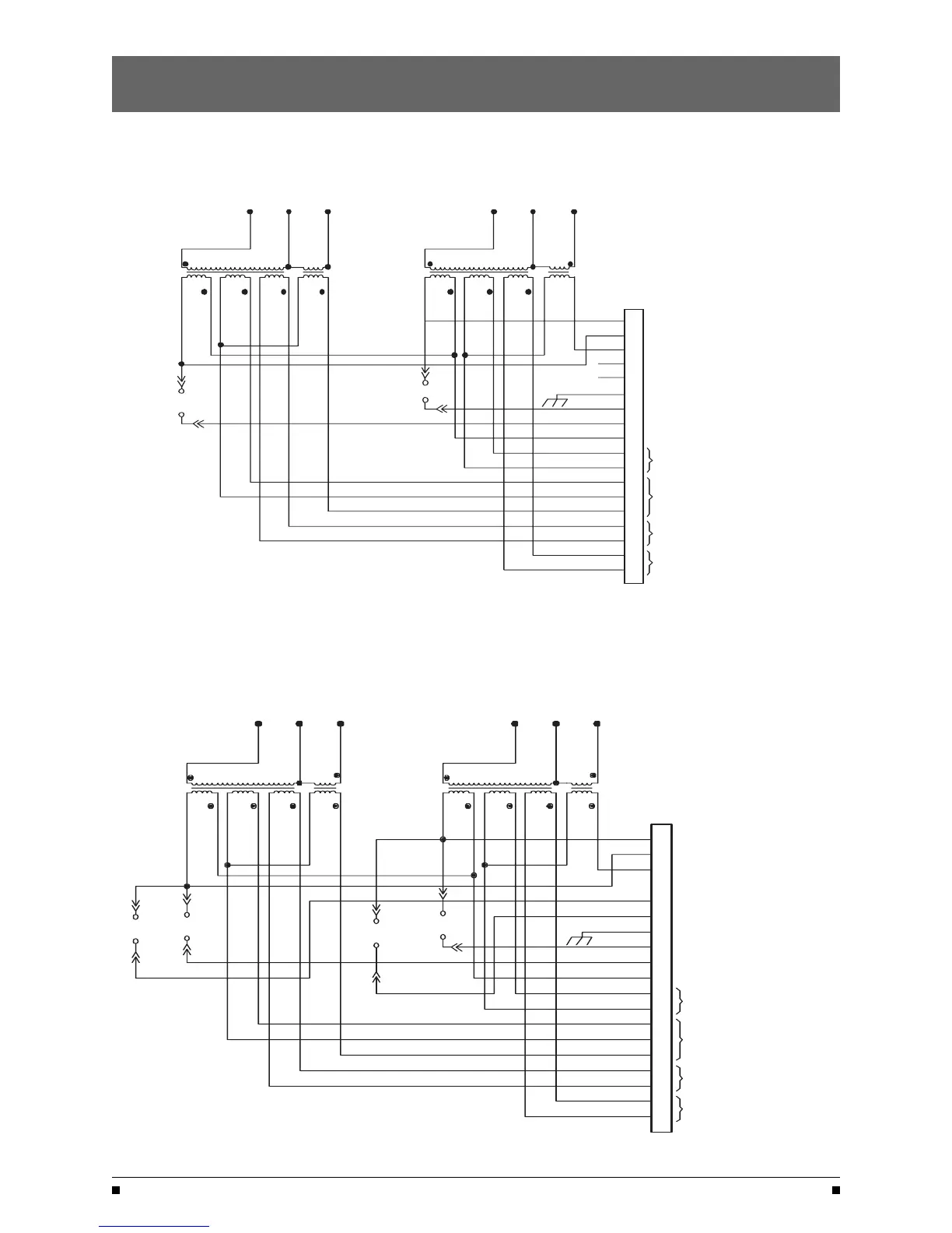
Figure 18
Figure 19
Standard Transition CPS Schematic
Delayed Transition CPS Schematic
Controls Power Supply (CPS)
(cont’d)
GND
903
902
801
901
807
804
803
904
905
906
805
806
(BLANK)
(BLANK)
GROUND
C.V. SCR-E CONTROL VOLTAGE (SOURCE 2)
COMMON
J5
24V 10V 11V
XE1
30 31
24V 10V 11V 10V
XN1 XN2
20 21 22
XN1 -
XN2 -
XE1 -
SOURCE 1 CONTROL TRANSFORMER
SOURCE 1 3 PHASE SENSING
TRANSFORMER
SOURCE 2 CONTROL TRANSFORMER
3 PHASE SOURCE 2
SINGLE PHASE SOURCE 2 SENSING
3-PHASE SOURCE 1 SENSING
SOURCE 1 CONTROL POWER
SOURCE 2 CONTROL POWER
800
902
804
803
805
806
804
807
900
902
904
903
905
906
800
900
SOURCE 2 24V OUTPUT
SOURCE 1 24V OUTPUT
(18)
(1)
32
XE2
907
904
907
XE2 - SOURCE 2 3 PHASE SENSING TRANSFORMER
808
908
C.V. SCR-N CONTROL VOLTAGE (SOURCE 1)
JC
C.V.
SCR-N
801
JC
JC
JC
C.V.
SCR-E
C.V. SCR-N CONTROL VOLTAGE (SOURCE 1)
C.V. SCR-E CONTROL VOLTAGE (SOURCE 2)
C.V. SCR-EO CONTROL VOLTAGE (OPEN SOURCE 2)
C.V. SCR-NO CONTROL VOLTAGE (OPEN SOURCE 1)
SCR-NO
JC
908
JC
C.V.
SCR-E
C.V.
901
JC
JC
908
808
JC
SCR-EO
C.V.
JC
JC
801
JC
SCR-N
C.V.
GND
907
903
902
801
901
807
804
803
904
905
906
805
806
GROUND
COMMON
J5
24V 10V 11V 10V24V 10V 11V 10V
XN1 XN2
20 21 22
XN1 -
XN2 -
XE1 -
XE2 -
SOURCE 1 CONTROL TRANSFORMER
SOURCE 1 3 PHASE SENSING
TRANSFORMER
SOURCE 2 CONTROL TRANSFORMER
SOURCE 2 3 PHASE SENSING
TRANSFORMER
SINGLE PHASE SOURCE 2 SENSING
3-PHASE SOURCE 1 SENSING
SOURCE 1 CONTROL POWER
SOURCE 2 CONTROL POWER
800
902
804
803
805
806
804
807
900
902
904
903
905
906
904
907
800
900
SOURCE 2 24V OUTPUT
SOURCE 1 24V OUTPUT
(18)
(1)
908
808
XE1
30
XE2
31 32
3-PHASE SOURCE 2 SENSING
 Loading...