10
WARNING: To avoid possible electric
shock, be sure electricity is turned
off at the main fuse box before wiring.
NOTE: Fan must be installed at
a maximum distance of 6 m (20
ft.) from the transmitting unit for
proper signal transmission between
the transmitting unit and fan’s
receiving unit.
CAUTION: Do not use wall switch
with dimmer function.
WARNING: Check to see that all
connections are tight, including
ground wire, and that no bare wire
is visible at the wire nuts, except for
the ground wire.
WARNING: Electrical diagrams are
for reference only. Optional use of
any light kit shall be cUL listed and
marked suitable for use with this fan.
MAKING THE ELECTRICAL CONNECTIONS
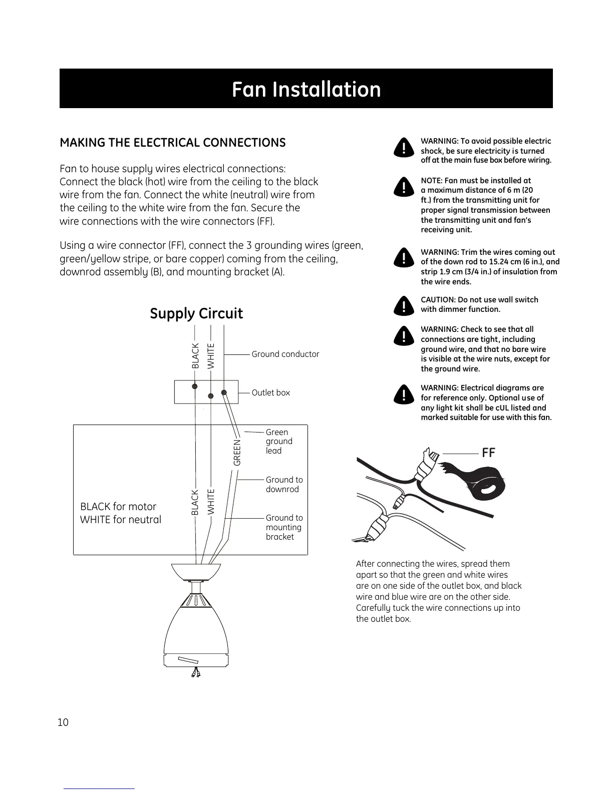
Supply Circuit
Fan to house supply wires electrical connections:
Connect the black (hot) wire from the ceiling to the black
wire from the fan. Connect the white (neutral) wire from
the ceiling to the white wire from the fan. Secure the
wire connections with the wire connectors (FF).
Using a wire connector (FF), connect the 3 grounding wires (green,
green/yellow stripe, or bare copper) coming from the ceiling,
downrod assembly (B), and mounting bracket (A).
Fan Installation
WARNING: Trim the wires coming out
of the down rod to 15.24 cm (6 in.), and
strip 1.9 cm (3/4 in.) of insulation from
the wire ends.
BLACK for motor
WHITE for neutral
FF
After connecting the wires, spread them
apart so that the green and white wires
are on one side of the outlet box, and black
wire and blue wire are on the other side.
Carefully tuck the wire connections up into
the outlet box.
Ground conductor
Outlet box
Green
ground
lead
Ground to
downrod
Ground to
mounting
bracket
BLACK
WHITE
WHITE
BLACK
GREEN