1–168 345 TRANSFORMER PROTECTION SYSTEM – COMMUNICATIONS GUIDE
MODBUS MEMORY MAP CHAPTER 1: COMMUNICATIONS GUIDE
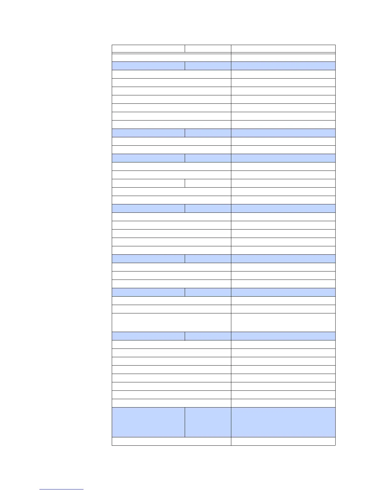
0x0040 Contact Input 1
FC204B unsigned 16 bits Contact Input Bit Field Values (Subset B)
0x0000 Disabled
0x0044 Contact Input 5
0x0045 Contact Input 6
0x0046 Contact Input 7
0x0047 Contact Input 8
0x0048 Contact Input 9
0x0049 Contact Input 10
FC204C unsigned 16 bits Contact Input Bit Field Values (Subset C)
0x0000 Disabled
0x0041 Contact Input 2
FC204D unsigned 16 bits Contact Input Bit Field Values (Subset D)
0x0000 Disabled
0x0042 Contact Input 3
FC204F unsigned 16 bits Contact Input Bit Field Values (Subset F)
0x0000 Disabled
0x0042 Contact Input 4
FC205 unsigned 16 bits Element Type 1
0 Disabled
1Alarm
2 Latched Alarm
3Trip
4 Control
FC206 unsigned 16 bits Element Type 2
0 Disabled
1Alarm
2 Latched Alarm
FC214 unsigned 16 bits MAC Address
MSB Leftmost Character
LSB Right Side Character
The hex value stored in each byte must be
displayed as it's equivalent ASCII value (e.g.,
0xFE must be displayed as FE)
FC215 unsigned 32 bits GOOSE Receive Status
0x0001 GOOSE 1 RECEIVED
0x0002 GOOSE 2 RECEIVED
0x0004 GOOSE 3 RECEIVED
0x0008 GOOSE 4 RECEIVED
0x0010 GOOSE 5 RECEIVED
0x0020 GOOSE 6 RECEIVED
0x0040 GOOSE 7 RECEIVED
0x0080 GOOSE 8 RECEIVED
FC216 unsigned 16 bits Received GOOSE Message Formatting Bit
Field TTTTTTTTSSSSSSSS S-Bits denote the
text string type T-Bits denote the length of the
string associated with the text string type,
and is handled by the firmware
0x00FF Row
Code Type Definition

 Loading...


