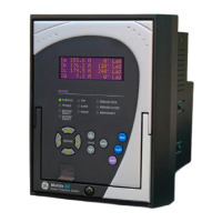
350 * * * * * * * * * * * *
Interface 350 |||||||||||| 350 Feeder Protection System
User Interface E | | | | | | | | | | | English without programmable LEDs
L | | | | | | | | | | | English with programmable LEDs
Phase Currents
a
a. Phase Current options PX/P0 and Ground Current options GX/G0 are only available with the non-drawout Case Design N.
PX|||||||||| No CT
P0|||||||||| 1 A or 5 A configurable phase current inputs
P1|||||||||| 1 A 3-phase current inputs
P5|||||||||| 5 A 3-phase current inputs
Ground Currents
b
b. Ground Currents G1/G5 and S1/S5 must match the corresponding P1/P5 Phase Currents (i.e. 5A and 1A must not be mixed).
Ground Current GX requires PX Phase Current, and is only available with Case N, Current Protection N, Other Options V, and Input/Output E.
Ground Current G0/S0 must match the P0 Phase Current, and is only available with the non-drawout Case Design N.
GX | | | | | | | | | No CT
G0 | | | | | | | | | 1 A and 5 A configurable ground current input
G1 | | | | | | | | | 1 A ground current input
G5 | | | | | | | | | 5 A ground current input
S0 | | | | | | | | | 1 A or 5A configurable sensitive ground current input
S1 | | | | | | | | | 1 A sensitive ground current input
S5 | | | | | | | | | 5 A sensitive ground current input
Power Supply L | | | | | | | | 24 to 48 V DC
H|||||||| 125 to 250 V DC/120 to 230 V AC
Input/Output
c
c. Input/Output option A is only available with the non-drawout Case Design N
E | | | | | | | Standard (10 Inputs, 7 relay outputs)
A | | | | | | | Standard (10 inputs, 5 relay outputs, 2 MOSFET loads) + 4 Arc Flash detectors
Current Protection
d
d. Current Protection option S has been discontinued.
N|||||| None (voltage and frequency relay, requires a PX/GX configuration)
E
|
|
|
|
|
|
|
|
|
|
|
|
Extended configuration: User selectable 49, 50P(2), 50G/SG(2), 50N(2), 51P(1), 51G/SG(1),
51N(1)
M
|
|
|
|
|
|
|
|
|
|
|
|
Advanced configuration: Extended + 51_2 or 46(1), 50_2 (1) or 46(1),
I1/I2(46BC)
Control N | | | | | CLP, Lockout (86)
C | | | | | CLP, 50BF, Lockout (86), Autoreclose (79)
Other Options
e
e. CLP, 79, and 50BF are not supported when V is selected under Other Options.
N| | | | No selection
V
|
|
|
|
|
|
|
|
27P(4), 27X(1), 27P_1(1), 59P(4), 59N(4), 59X(1), 59_2(2), 81O(4), 81U(4), 25(1), VTFF(1), 24(1),
Voltage Metering (requires a PX/GX configuration)
D| | | | Neutral and Ground Directional Overcurrent Protection: 67N(1), 67G/SG(1), 60CTS
M| | | | Voltage, Power, and Energy Metering, 60CTS
R
|
|
|
|
|
|
|
|
Phase, Neutral, and Ground Directional Overcurrent Protection: 67P(1), 67N(1), 67G/
SG(1), 32N(2), VTFF + Voltage, Power, and Energy Metering, 60CTS
P
|
|
|
|
|
|
|
|
|
|
|
|
Extended Protection: 27P(2), 27X(1), 27P_1 (1), 59P(2), 59N(1), 59X(1), 59_2(1), 81O(2),
81U(2), 67P(1), 67N(1), 67G/SG(1), VTFF(1), 25(1), 60CTS, Voltage, Power, and Energy
Metering
W| | | | Advanced Protection: Extended + 32(2)
Communications
f
f. Communications option 4E allows the selection of either IEC 61850 or OPC-UA; both cannot be used at the same time.
Communications option 5E is only available with Case Design D or X. 898800AA.PDF
S N | | Standard: Front USB, Rear RS485: Modbus RTU, DNP3.0, IEC60870-5-103
1 E
|
|
|
|
Standard + Ethernet (Copper & Fiber - MTRJ),
Modbus TCP/IP, DNP3.0, IEC 60870-5-104
2 E
|
|
|
|
Standard + Ethernet (Copper & Fiber - MTRJ),
Modbus TCP/IP, DNP3.0, IEC 60870-5-104, IEC 61850 GOOSE
3 E
|
|
|
|
Standard + Ethernet (Copper & Fiber - MTRJ),
Modbus TCP/IP, DNP3.0, IEC 60870-5-104, IEC 61850
4 E
|
|
|
|
Standard + Ethernet (Copper & Fiber - MTRJ),Modbus TCP/IP, DNP3.0, IEC 60870-5-104,
IEC 61850, OPC-UA
5 E
|
|
|
|
Standard + Ethernet (Dual Fiber - MTRJ),Modbus TCP/IP, DNP3.0, IEC 60870-5-104, IEC
61850, OPC-UA, PRP, HSR, 1588, PTP
Case Design D | Protection Relay with drawout design
N| Protection Relay with non-drawout design
X| Protection Relay (drawout design) with no chassis
Harsh Environment N None
H Harsh Environment Conformal Coating

 Loading...