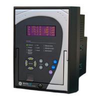
350 FEEDER PROTECTION SYSTEM – QUICKSTART GUIDE
Table of Contents
1. INTRODUCTION Overview ................................................................................................................................1
Description of the 350 Feeder Protection System..............................................2
350 order codes..................................................................................................................5
Specifications.......................................................................................................................9
Password security....................................................................................................................9
Protection.....................................................................................................................................9
Metering........................................................................................................................................14
Data capture ..............................................................................................................................14
Control...........................................................................................................................................15
Monitoring....................................................................................................................................17
Inputs .............................................................................................................................................17
Outputs..........................................................................................................................................18
Power supply..............................................................................................................................20
Communications ......................................................................................................................21
Testing and certification .......................................................................................................22
Physical.........................................................................................................................................23
Environmental............................................................................................................................24
2. INSTALLATION Mechanical installation ...................................................................................................25
Dimensions..................................................................................................................................26
Product identification .............................................................................................................28
Mounting ......................................................................................................................................28
Standard panel mount .........................................................................................................28
Mounting using the S1/S2/MDP/IAC or SR735 adapter plate............................32
Drawout unit withdrawal and insertion.........................................................................35
IP20 Cover (optional) ...............................................................................................................36
Arc flash sensors.......................................................................................................................37
Sensor fiber handling & storage ......................................................................................38
Point sensor installation ......................................................................................................39
Loop sensor installation.......................................................................................................43
Electrical installation ........................................................................................................46
Typical wiring diagrams........................................................................................................47
350 Terminal identification..................................................................................................49
Wire range...................................................................................................................................52
Phase sequence and transformer polarity..................................................................52
Current inputs ............................................................................................................................53
Ground and sensitive ground CT inputs ........................................................................53
Zero sequence CT installation............................................................................................54
Voltage inputs............................................................................................................................55
Control power ............................................................................................................................55
Contact inputs ...........................................................................................................................56
Trip and Close output relays...............................................................................................57
Serial communications..........................................................................................................59
IRIG-B .............................................................................................................................................60
3. INTERFACES Front control panel interface........................................................................................62
Description ..................................................................................................................................63
Display...........................................................................................................................................64
Working with the Keypad...................................................................................................64

 Loading...