Do you have a question about the GE DCVH480EK0WW and is the answer not in the manual?
Information intended for individuals with adequate technical experience. Repair risks are highlighted.
Crucial warning to disconnect power before servicing to avoid injury or death.
Requirement to properly reconnect grounding wires, screws, straps, clips, nuts, or washers.
Details PPE requirements like safety glasses, cut-resistant gloves, and steel toe shoes for all repairs.
Outlines warranty coverage, exclusions, and customer service contact information for GE dryers.
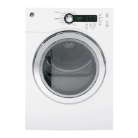
Shows where to find the model and serial number plate on the dryer.
Indicates the location of the mini manual, which is behind the control panel.
Describes the function of various control panel selections and adjustments.
Instructions for locking and unlocking the control panel using the TEMP and SENSOR pads.
Explains the Damp Alert option, its beep notification, and applicable sensor dry selections.
Details the option to stack the dryer on a washer and the required stacking kit.
Provides safety warnings and minimum clearance requirements for alcove or closet installations.
Step-by-step guide for installing the stacking bracket kit, including removing leveling legs and adding rubber pads.
Steps to install the bracket to the washer and dryer, and safely slide the stacked unit into place.
Details 3-wire and 4-wire connection requirements and the use of UL recognized strain relief.
Preparation steps, hardware used, and tools required for reversing the dryer door swing.
Instructions for disassembling the door, removing screws, and rotating window/inner face.
Steps to replace door screws, latch, and reattach hinge with mounting screws.
Procedure to remove the door and hinge assembly by unscrewing specific fasteners.
Identifies the lint screen's location within the dryer drum.
Explains how the lint screen unfolds for easier cleaning.
Describes checking the door switch functionality using the service 'Test Mode'.
Instructions to remove a specific clip for door switch replacement, noting it's for factory use only.
Shows the drum lamp assembly and its mounting groove in the rubber housing.
Details LED lighting, power supply, accessibility from the front, and operating conditions for the drum lamp.
Procedure to remove the top panel by unscrewing and sliding it towards the rear.
Identifies screws securing the control panel and how to lift and pull it forward.
Shows the location of the main PCB assembly after control panel removal.
Instructions for removing the control knob and noting shaft alignment for reinstallation.
Details the removal of four Phillips screws securing the PCB.
Explains how to press locking tabs to release the PCB from its mounting.
Notes that rubber push buttons are available as a separate part for replacement.
Notes that plastic push buttons are available as a separate part for replacement.
Instructions to remove the front panel by unscrewing and lifting it off the base.
Details removing the front drum support and disconnecting sensor/lamp harnesses.
Procedure for unlocking the front drum support by sliding and dropping to release the upper tab.
Shows drum rollers mounted to the support and how to remove them using a retainer clip.
Details filter inlet assembly removal, sensor wiring disconnection, and testing.
Instructions for removing the filter inlet assembly by unscrewing and lifting it out.
Shows removing rear cover screws to access the belt and idler pulley for removal.
Instructions to release belt tension by pushing the idler and remove the belt from the motor pulley.
Details the idler assembly attachment to the motor bracket via a Phillips head shoulder screw and spring.
Steps to slide the drum assembly forward and remove it from the dryer cabinet.
Information regarding potential damage to the rear drum shaft and bearing replacement.
Identifies felt gasket assembly, bracket, and the rear drum bearing assembly.
Instructions to remove felt gasket bracket screws and note the 'UP ARROW' for reassembly.
Details the 'UP ARROW' for reassembly and how the gasket attaches with dart tabs.
Shows the belt switch secured to the motor bracket with a single Phillips head screw.
Explains the belt switch as normally closed and its function when the belt breaks.
Instructions to remove the two Phillips screws securing the blower housing cover.
Procedure for removing the blower wheel, including holding the shaft and removing the 14mm nut.
Locates outlet thermostat and thermistor inside blower housing, removed by one screw.
Details disconnecting motor harness, removing clamps, and removing blower wheel for motor access.
Lists wire colors and corresponding connections for testing centrifugal switch and thermostat on the motor.
Illustrates airflow paths and heater location within the dryer's rear view.
Shows removing the rear cover to access the heater assembly and airflow path.
Highlights the location of the cool air intake within the dryer's airflow system.
Instructions to remove the two Phillips screws securing the heater assembly.
Describes the heater assembly features dual elements (600W/1600W) and replacement as a complete unit.
Procedure for removing the protective grommet and disconnecting heater wire harnesses.
Shows the complete heater assembly including its harness and thermostat components.
States that thermostats are not replaceable and the entire heater assembly must be replaced.
Provides resistance values (Ohms) and amp ratings for the 1600W and 600W heater elements.
Lists thermistor resistance values in K OHMS corresponding to specific temperatures in °F.
Details temperature points (°F) for opening and closing of outlet control, high-limit, and inlet safety thermostats.
Diagram showing the wiring connections to the PCB for various components like Door Switch and Heaters.
Identifies key connectors (CN1, CN2, CN4) and relays (RY1, RY6) on the main PCB.
Details pin assignments for Thermistor, Touch sensor, and Drum Lamp on connector CN4.
Explains how connector CN2 senses the door switch and its functions for drum lamp and motor.
Provides resistance values for testing motor windings and troubleshooting open circuits.
Details resistance tests for heater elements and the Hi Limit Thermostat on the PCB.
Instructions on how to enter the Service Test Mode from an idle state.
Indicates that 'T01' will appear in the display upon entering the service test mode.
Explains using the rotary knob to advance selections and START/PAUSE to initiate test sequences.
Details how to return to test selections or exit the service mode using the POWER button.
Lists various service tests, their sequences, and key notes for execution.
Provides a table of error codes, their descriptions, and corrective actions for troubleshooting.
Diagram of the electronic control, showing component connections and wiring.
| Brand | GE |
|---|---|
| Model | DCVH480EK0WW |
| Type | Electric Dryer |
| Color | White |
| Voltage | 240 V |
| Amperage | 30 A |
| Drum Material | Aluminized alloy |
| Control Type | Electronic |
| Number of Temperature Settings | 4 |
| Wrinkle Care Option | Yes |
| Moisture Sensor | Yes |
| Energy Star Certified | No |
| Timed Dry | Yes |
| Width | 27 inches |
| Dryer Cycle Selections | Heavy Duty, Normal, Delicate |