Installation instructions
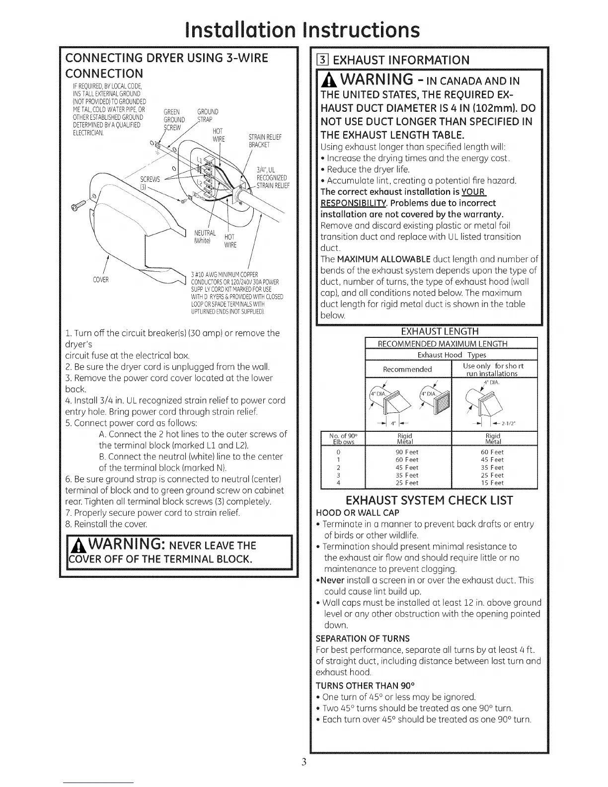
CONNECTING DRYER USING 3-WIRE
CONNECTION
IFREQUIRED,BYLOCALCODE,
iNSTALLEXTERNALGROUND
(NOTPROVIDED)TOGROUNDED
METAL,COLDWATERPIPE,OR GREEN GROUND
OTHERESTABLISHEDGROUND GROUND STRAP
DETERMINEDBYAQUALiFiED SCREW
ELECTRiCiAN. HOT
WiRE STRAINRELIEF
BRACKET
3/#',UL
RECOGNIZED
NEUTRAL
(White) HOT
WIRE
COVER
] #10 AWGMINIMUMCOPPER
CONDUCTORSOR120/240V30APOWER
SUPPLYCORDKiTMARKEDFORUSE
WiTHDRYERS& PROVIDEDWiTHCLOSED
LOOPORSPADETERMINALSWiTH
UPTURNEDENDS(NOTSUPPLIED}.
1.Turn off the circuit breaker(s) (30 amp) or remove the
dryer's
circuit fuse at the electrical box.
2. Besure the dryer cord is unplugged from the wall.
3. Removethe power cord cover located at the lower
back.
4. Install 3/4 in. UL recognized strain relief to power cord
entry hole. Bring power cord through strain relief.
5.Connect power cord as follows:
A. Connect the 2 hot linesto the outer screws of
the terminal block (marked L1 and L2).
B.Connect the neutral (white) line to the center
of the terminal block (marked N).
6. Besure ground strap is connected to neutral (center)
terminal of block and to green ground screw on cabinet
rear.Tighten all terminal block screws (3)completely.
7. Properly secure power cord to strain relief.
8. Reinstall the cover.
j|WARNING'. NEVER LEAVE THE j
COVER OFF OF THE TERMINAL BLOCK.
EXHAUST INFORMATION
WARNING -IN CANADAANDIN
THE UNITED STATES, THE REQUIRED EX-
HAUST DUCT DIAMETER IS 4. IN (102mm). DO
NOT USE DUCT LONGER THAN SPECIFIED IN
THE EXHAUST LENGTH TABLE.
Using exhaust longer than specified length will:
, Increase the drying times and the energy cost.
, Reduce the dryer life.
, Accumulate lint, creating a potential fire hazard.
The correct exhaust installation is YOUR
RESPONSIBILITY.Problems due to incorrect
installation are not covered by the warranty.
Remove and discard existing plastic or metal foil
transition duct and replace with UL listed transition
duct.
The MAXIMUM ALLOWABLEduct length and number of
bends of the exhaust system depends upon the type of
duct, number of turns, the type of exhaust hood (wall
cap), and all conditions noted below. The maximum
duct length for rigid metal duct is shown in the table
below.
EXHAUST LENGTH
RECOMMENDED MAXIMUM LENGTH
Exhaust Hood Types
Useonly for sho rt
Recommended
run installations
4" DIA.
4" I-_ I-4_ 2 1/2"
No. of 90 ° Rigid Rigid
EIbows Metal Metal
0 90 Feet 60 Feet
1 60 Feet 45 Feet
2 45 Feet 35 Feet
3 35 Feet 25 Feet
4 25 Feet 15 Feet
EXHAUST SYSTEM CHECK LIST
HOOD OR WALL CAP
, Terminate in a manner to prevent back drafts or entry
of birds or other wildlife.
, Termination should present minimal resistance to
the exhaust air flow and should require little or no
maintenance to prevent clogging.
,Never install a screen in or over the exhaust duct. This
could cause lint build up.
, Wall caps must be installed at least 12 in. above ground
level or any other obstruction with the opening pointed
down.
SEPARATIONOFTURNS
Forbest performance, separate all turns by at least 4 ft.
of straight duct, including distance between last turn and
exhaust hood.
TURNSOTHERTHAN 90°
, One turn of 45oor less may be ignored.
, Two 45oturns should be treated as one 90oturn.
, Eachturn over 45o should be treated as one 90oturn.
3
 Loading...