18 RSTi-EP Slice I/O Serial Communication Module
GFK-2992B
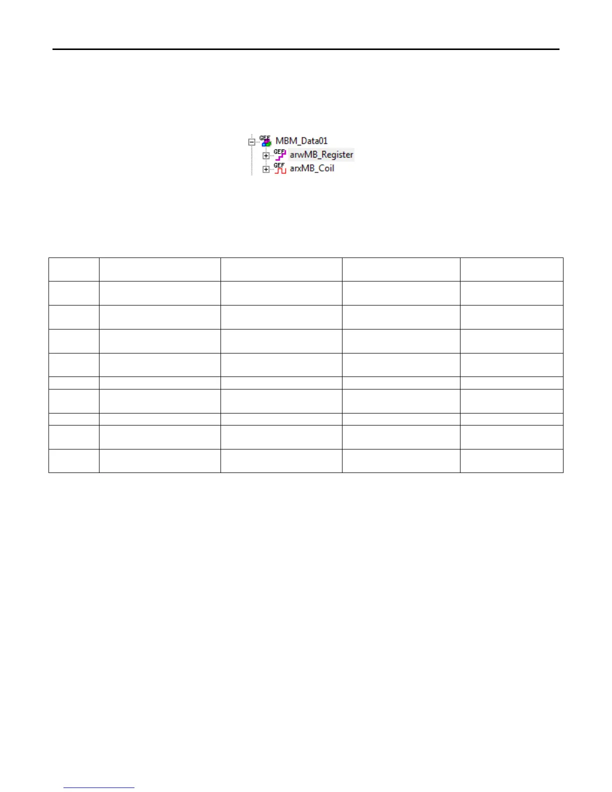
To enable MODBUS data access, a User Defined Types MBM_Data must be imported.
To use the variables, an instance of this UDT must be built.
Every data transfer on the bus is initiated and controlled by the master. A high level on the input varible xMODfcStrobe
starts the job, and its function is determined by the function code entered at the input variable usiMODfc.
Communication with the MODBUS station, for which an address has been parameterized on the input variable
usiMODslaveAdr, is accepted. Depending on the function code, the MODBUS input parameters are interpreted as listed
in the following table.
uiMODdatOff uiMODdatNr warMODRegister xarMODCoil
FC 1 Coil source offset in slave
Number of requested
coils
---
Coil target buffer in
master
FC 2
Input source offset in
slave
Number of requested
inputs
---
Input target buffer in
master
FC 3
Holding register source
offset in slave
Number of requested
registers
Holding register target
buffer in master
---
FC 4
Input register source
offset in slave
Number of requested
registers
Input register target
buffer in master
---
Coil target offset in slave
FC 6
Holding register target
offset in slave
---
Register value in index [1]
---
FC 15 Coil target offset in slave Number of coils to be sent ---
Coil source buffer in
master
FC 16
Holding register target
offset in slave
Number of registers to be
sent
Holding register source
buffer in master
---
Buffers warMODRegister and xarMODCoil are always Read or Written by the master from the first index (MODBUS to 1).
The MODBUS diagnostic outputs usi_MODslaveAdrDone, usiMODfcDone, uiMODdatOffDone, and uiMODdatNrDone,
always mirror the communication state during a malfunction, meaning they acknowledge the respective inputs or
provide information concerning the content of the slave response. With function codes 5, 6 and 8, uiMODdatNrDone
describes the written value. The output xMODtransActive is TRUE during execution, until the slave response is received.
After the job has been completed, the output returns to FALSE and xMODtransOk is set to a value of 1 if no telegram
fault, protocol fault, data fault, or other communication fault has occurred. During a fault, xMODtransOk remains at
FALSE and the fault is described with the usiMODfailCode exception code. If the slave does not answer within the set
tMODtimeOut timeout threshold, an error message is generated. The outputs are refreshed each time a new job is
started.
For public disclosure
 Loading...