EasyManua.ls Logo

GE GFWN1600J - User Manual

GE GFWN1600J
70 pages
To Next Page IconTo Next Page
Loading...
GE Appliances
Louisville, Kentucky 40225
31-9261
GE Appliances Front Load Washer
Technical Service Guide
December 2016
GE Appliances
GFWS1705H
GFWS1700H
GFWN1600J
GFWN1300J
GFWH1200H
GFWN1100H
GFW400SCK
GFW450SPK
GFW450SSK
Question and Answer IconNeed help?

Do you have a question about the GE GFWN1600J and is the answer not in the manual?

GE GFWN1600J Specifications

General IconGeneral
BrandGE
ModelGFWN1600J
CategoryWasher
LanguageEnglish

Summary

Safety Information

Important Safety Notice

General safety notice for service personnel regarding potential hazards.

Reconnect Grounding Devices

Procedure to ensure proper grounding of appliance components after servicing.

Safety Requirements

Lockout;Tagout (LOTO) Process

Mandatory 6-step process for technicians before disassembling the appliance.

Control Features

Control Panel Layouts

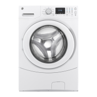
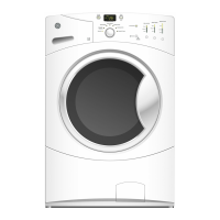
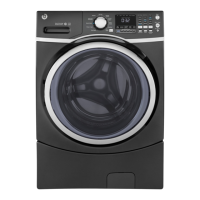
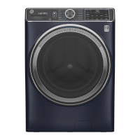
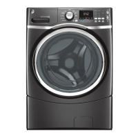
Diagrams and explanations of control panel layouts for different GE washer models.

Washer Features

Wash Cycles and Options

Details on various wash cycles (e.g., Sanitize, Steam) and basic options.

Using the Washer

Dispenser Operation and Loading

Instructions for using the dispenser drawer and loading the wash drum properly.

Operation Overview

Basic Wash Cycle Steps

Step-by-step guide for initiating and performing a basic wash cycle.

Component Locator Views

Component Identification Diagrams

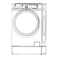
Diagrams showing the location of key components from top, front, and other views.

Control and Inverter Board Connections

Washer Components and Control Panel

Control Board Operations

Door Lock and Strike

Dispenser Assembly and Motor

Water Level Sensor and Valve

Water Valve and Pump

Pump Removal

Heater Assembly and Thermistor

Inverter and Motor Assembly

Door Components

Door Hinge and Tub Gasket

Dampers

Wash Basket Removal

Outer Tub Assembly and Suspension

Service Test Mode

Entering and Exiting Test Mode

Instructions on accessing and exiting the service test mode for diagnostic purposes.

Available Test Modes and Functions

List of test modes (t01-t13) and their functions for verifying component operation.

Fault Codes

Troubleshooting Fault Codes

List of fault codes (E22-E67), descriptions, problems, and potential causes/actions for troubleshooting.

Schematics Diagram

Related product manuals