EasyManua.ls Logo

GE GTDS825EDMC User Manual

GE GTDS825EDMC
86 pages
To Next Page IconTo Next Page
Page #1 background imageLoading...
Page #1 background image
2
Copyright General Electric 2012
12/3/2012
GTDP740EDWW/GDWW
GTDL740EDWW/GDWW
GTDS810EDWS/GDWS
GTDS815EDMC/GDMC
GTDS820EDWS/GDWS
GTDS825EDMC/GDMC
GHDS830EDWS/GDWS
GHDS835EDMC/GDMC
GTDS850EDWS/GDWS
GTDS855EDMC/GDMC
GTDS860EDWS/GDWS
GTDS865EDMC/GDMC
GE Appliance Park Proudly Presents
The Newly Designed GE Dryers For 2012
Colors
White/ White Silver Metallic/Carbon

Other manuals for GE GTDS825EDMC

Question and Answer IconNeed help?

Do you have a question about the GE GTDS825EDMC and is the answer not in the manual?

GE GTDS825EDMC Specifications

General IconGeneral
Colormetallic carbon
Dryer Capactity7.8 cubic feet
Number of Cycles13
Stackableno
Ventingyes
Temperature Controlyes
Control Typeelectronic
Delay Startyes
Cycle Signalyes
Interior Lightyes
Drying Rackno
Moisture Sensor Optionyes
Steamyes
Current25 amperes
Weight and Dimensions IconWeight and Dimensions
Depth31.9 inches
Height44.5 inches
Width28 inches
Net Weight130 pounds

Summary

Important Safety Notice

General Warning

General warning about disconnecting power before servicing and following checks.

Grounding Device Reconnection

Instructions to reconnect all grounding devices properly after service.

Electric Dryer Schematic

AC Voltage and Motor Switch Wiring

Diagram detailing AC voltage input to the board and motor switch wiring.

Gas Dryer Schematic

AC Voltage to the Board Wiring

Diagram showing AC voltage connection to the power board for gas dryers.

Service Mode Navigation

Entering and Operating Service Mode

Instructions on how to enter service mode, navigate tests, and exit.

Service Mode Tests

Test Functions and Descriptions

Details of various service mode tests, their display codes, and remarks.

Service Mode Fault Codes

Understanding Fault Codes

Explanation of fault codes, SSD display, and how to check/clear errors.

Service Mode Model ID Table

Model Identification Mapping

Table mapping dryer model numbers to their descriptions and model IDs.

Electrical Requirements

Resistance and Voltage Readings

Resistance Values - Continued

Main Board Connector Locations

Diagram of Connectors

Visual guide showing the location of various connectors (J2, J4, J5, J7, J8, J10, J11, J25) on the main board.

Sensor Rod Diagnostics

Testing Sensor Rods

Procedure to test sensor rods using the J25 connector for voltage drop and continuity.

LED Light Diagnostics

Inlet Thermistor Diagnostics

Checking Inlet Thermistor Resistance

Procedure to check inlet thermistor resistance using the J10 connector and white wires.

Outlet Thermistor Diagnostics

Checking Outlet Thermistor Resistance

Procedure to check outlet thermistor resistance using the J10 connector and blue wires.

Heater Resistance Diagnostics

Measuring Heater Resistance

Procedure to measure heater resistance between J7 (white) and J2 (blue) connectors.

Heater Voltage Diagnostics

Checking Heater Voltage

Procedure to check heater voltage from J7/J2 to J8/J5 connectors.

Dead Board Diagnostics

Troubleshooting a Non-Responsive Board

Steps to check voltage, continuity, and fuses for a dead board.

Water Valve Diagnostics

Gas Valve Diagnostics

Motor Resistance Diagnostics

Measuring Motor Resistance

Procedure to check resistance of drum motor windings and blower motor.

Electrical Connection Information

Standard Electric Dryer Hookup

Details on branch circuit, fuses/breakers, voltage, and amperage for electric dryers.

Mobile Home Installation

Specific requirements for connecting dryers in mobile home installations using a 4-wire connection.

Power Cord Replacement

Leveling and Stabilizing

Backsplash Removal

Backsplash Removal - Hex Screws

Backsplash Removal - Rear Access

Top Cover Removal

Top Cover Removal - Final Lift

Front Panel Removal

Front Panel Removal - Component Detachment

Drum Removal

Drum Removal - Belt and Support

Electric Thermistor and Thermostat Locations

Gas Thermistor and Thermostat Locations

Rear Roller Support Bulkhead Removal

Blower Removal

Heater Removal - Electric

Disconnecting Wires and Removing Heater

Steps to disconnect power wires and remove the heater assembly.

Heater Removal - Gas

Gas Heater Component Access

Overview of accessing gas heater components and their related parts.

Gas Valve Assembly Removal

Removing the Gas Valve

Instructions for disconnecting connectors and removing the gas valve assembly.

Main Burner Assembly Removal

Removing the Main Burner

Steps to remove the main burner from its mounting bracket.

Glow Bar Replacement - Gas

Replacing the Glow Bar

Instructions to unplug the connector and remove the burner assembly to replace the glow bar.

Glow Bar Replacement - Igniter Access

Changing Igniter Without Full Assembly Removal

Note on changing the igniter without removing the complete assembly.

Flame Sensor Removal

Water Valve Removal

Water Valve Removal - Final Steps

Troubleshooting Tips

Dryer Not Starting or Heating

Common causes and solutions for dryers that won't start or won't heat.

Dryer Shaking or Greasy Spots

Troubleshooting for dryers that shake or leave greasy spots on clothes.
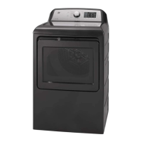
Troubleshooting Lint and Static

Troubleshooting Clothes Take Too Long to Dry

Troubleshooting Clothes Shrinkage and Wetness

Troubleshooting Cycle Completion Issues

Related product manuals