11
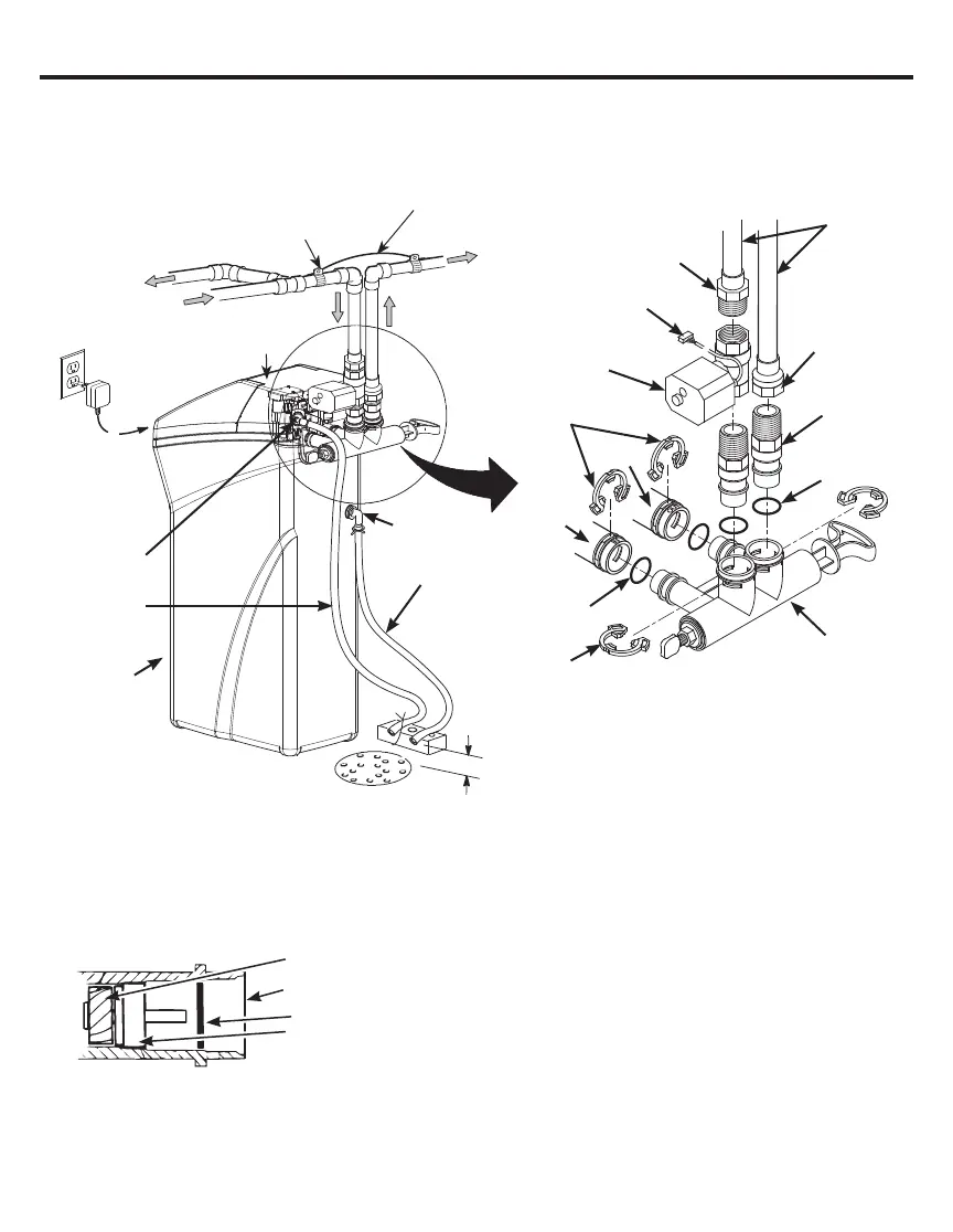
NOTE: Be sure the turbine and support are firmly in place
in the valve outlet. Blow into the valve port and observe the
turbine for free rotation.
• Remove plastic shipping plug and wire from valve outlet.
Figure 8
Turbine
Valve outlet
Turbine shaft and support
Plastic shipping plug
Inlet
Outlet
Lubricated
O-ring
Single Bypass
Valve
O-ring
1” NPTM
Threaded
Adaptor
1” NPTM
Threaded
Adaptor (not
included)
1” NPTF
Sweat
Adaptor
(not
included)
Pipe
1-1/2”
air gap
Floor Drain
Secure Valve Drain
Hose in place over Floor
Drain
Brine Tank
Overflow Hose*
Overflow
Adapter
Conditioned
Water
Main Water Pipe
Motorized Water
Shutoff valve
Plug into
controller
Plug-in
Transformer
To
Controller
Drain Hose
Adapter
Valve Drain
Hose*
*Do not connect the water
softener valve drain hose to
the brine tank overflow
NOTE: See “Air Gap Requirements” section.
Figure 6
Figure 7
Incoming
Hard Water
Hard Water
to Outside
Faucets
Top
Cover
Brine Tank
(Salt Storage)
Clips
Clips
Ground Wire
(not included)
Clamp
(not included)
TYPICAL INSTALLATION
Installation Instructions
 Loading...