Do you have a question about the GE IAC57A and is the answer not in the manual?
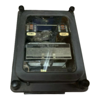
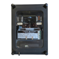
The General Electric Type IAC57A and IAC57B relays are long-time overcurrent relays designed for protection against overcurrents in single-phase and polyphase circuits. These relays are similar to the IAC51A and IAC51B types but are specifically modified to provide longer operating times. The device manual, GEI-19959J, along with insert booklet GEH-1753, provides comprehensive instructions for their installation, operation, and maintenance.
The core of the IAC57 relays is an induction unit, which is the basic component in all IAC relays. This unit features an induction-disk construction type, where the disk is actuated by a current operating coil on a laminated U-magnet. The disk shaft carries a moving contact that completes an alarm or trip circuit when it touches stationary contacts. A spiral spring restrains the disk shaft, setting the contact-closing current, while a permanent magnet retards its motion to achieve the correct time delay.
The IAC57A and IAC57B relays are primarily used to supply inverse time delay characteristics and to sound an alarm or trip circuit breakers for overload currents that cause their contacts to close. The IAC57A and IAC57B models are distinguished by their internal configurations, with the IAC57A having an internal connection diagram shown in Figure 11 of GEH-1753 and the IAC57B in Figure 12.
An integral part of these relays is the seal-in unit, mounted on the front left of the shaft. Its coil is in series, and its contacts are in parallel with the main contacts. When the main contacts close, the seal-in unit picks up and "seals in," raising a target into view. This target latches in the exposed position until released by pressing a button beneath the lower left corner of the cover.
Some IAC relays may also include an instantaneous unit, which provides instantaneous tripping for extremely high currents. This unit is a small hinge-type component, typically mounted on the right front side of the induction unit. Its contacts are normally connected in parallel with the main unit's contacts, and its coil is in series with the main unit's operating coil. When the current reaches a predetermined value, the instantaneous unit operates, closing its contact circuit and raising its target. The target latches in the exposed position until released by pressing a button.
Additionally, certain IAC relays can incorporate an A-C tripping unit for applications where D-C power is unavailable or A-C tripping is preferred. This unit is designed to energize a circuit breaker trip coil from its associated current transformer upon the main unit's operation. It transfers current from the current transformer secondary into the trip coil and removes it once the breaker trips. The tripping unit is mounted on the rear of the frame, opposite the tapped operating coil of the induction unit. Its operation involves the secondary current circulating through the induction unit current coil and the main coil of the REA auxiliary tripping unit. When the induction unit contacts close, the REA's shorting coil is short-circuited, causing a redistribution of flux that actuates the armature and the REA contacts. The opening of the REA contacts then directs the secondary current through the trip coil, tripping the breaker.
The IAC57 relays offer adjustable time and current settings to accommodate various protection requirements. The current at which the contacts operate can be changed by adjusting the position of the tap plug in the tap block at the top of the relay. The tap plug should be screwed firmly into the tap marked for the desired current, below which the unit is not intended to operate. When changing the current setting, the connecting plug must first be removed to short circuit the current transformer secondary circuit, then the tap plug screwed into the new tap, and finally the connecting plug replaced.
The pickup of the unit for any current tap is adjusted via a spring-adjusting ring. This ring can be turned with a screwdriver to bring the operating current into agreement with the employed tap setting or to achieve intermediate settings. The unit is factory-adjusted to close its contacts from any time-dial position at a minimum current within five percent of the tap-plug setting and resets at 90 percent of the minimum closing value.
The time setting is determined by the time dial. When the dial is set to "0," the contacts are just closed. Setting the dial to "10" requires the disk to travel the maximum amount, providing the maximum time setting. The primary adjustment for operation time is made with the time dial, but further fine-tuning can be achieved by moving the permanent magnet along its supporting shelf. Moving the magnet toward the disk shaft decreases the time, while moving it away increases it.
For selective action in systems with multiple relays, it is crucial to determine the maximum short-circuit current and choose time values for each relay that ensure proper sequence of operation, accounting for the time involved in breaker opening. A difference of about 0.5 seconds at maximum current is recommended between relays for selective operation, unless precise circuit time is known.
The target and seal-in unit's tap screw setting depends on the trip coil's operating current range. For currents from 0.2 to 2.0 amperes at minimum control voltage, the screw is set to the 0.2-ampere tap. For currents from 2 to 30 amperes, it's placed in the 2-ampere tap. Changing this setting involves removing the connecting plug, moving a screw from the left-hand stationary contact to the desired tap, then removing the screw from the other tap and placing it in the left-hand contact to prevent adjustment issues.
The IAC57 relays are factory-adjusted, and it is generally advisable not to disturb these adjustments. However, if adjustments are necessary, specific procedures must be followed.
For contact adjustment, the contacts should have approximately 1/32 inch wipe, meaning the stationary contact should deflect about 1/32 inch when the disk completes its travel. This wipe is adjusted by turning the screws in the contact brush. For relays with two circuit-closing contacts, the tips should be in the same vertical plane. When the time dial is set to "0," the contacts should just close. If incorrect, the dial can be regulated to read zero by loosening the screw clamping the arm to the shaft and turning the arm relative to the shaft.
Instantaneous unit adjustment involves selecting the desired current for operation and setting the adjustable pole piece so its hexagon head is even with the calibration scale. Raising or lowering the pole piece requires loosening the locknut, turning it, and then tightening it. The contacts should make at approximately the same time and have about 1/8 inch wipe, adjusted by loosening the screws holding the stationary contacts and moving them up or down.
For the A-C tripping unit, maintenance primarily involves occasional cleaning of the contacts. If adjustment is lost, it can be restored by ensuring the movable contact lies against the stationary contact with sufficient tension when de-energized, and the movable contact brush is free of kinks. The brass backing strip should be adjusted for a 1/16-inch contact gap with open contacts, and the compound bushing support adjusted so the back of the movable contact just touches the brass backing strip when the armature operates to open the contacts. The outer edge of the compound bushing should be about 1/32 inch from the inner edge of the stationary contact supporting post. Armature adjustment involves loosening two screws holding the armature-assembly bracket and sliding it until the armature just touches the pole face of the upper core, with about 1/32 inch clearance from the lower core. The bracket is then slid until the armature leaf spring is vertical and spaced clear of both armature and the vertical tip of the bracket. This ensures the armature is flush against the pole face of both cores, applies sufficient pressure, and prevents momentary contact opening or chattering.
Regular contact cleaning is essential. Fine silver contacts should be cleaned with a flexible burnishing tool, which has an etched roughened surface, resembling a superfine file. This tool removes corroded material without scratching the contacts. Knives, files, or abrasive paper/cloth should not be used, as they can cause scratches that increase arcing or leave insulating particles.
Periodic testing is recommended at least once every six months, including an operation test and inspection. Test connections are provided in Figure 18 of the manual.
When handling and storing relays, care must be taken to prevent damage. Relays should be stored in their original cartons in a moisture-free, dust-free, and metallic chip-free environment. Foreign matter can enter the case if the cover is removed, causing operational issues.
For drawout cases, it is crucial that the auxiliary brush is bent high enough to engage the connecting plug or test plug before the main brushes do, especially in current circuits with shorting bars. This prevents CT secondary circuits from being opened.
Renewal parts should be stocked in sufficient quantities for prompt replacement of worn, broken, or damaged components. When ordering, specify the quantity, part name, and complete nameplate data, including the General Electric Company requisition number if available. A recommended parts list can be found in Parts Bulletin number GEF-3883.
| Input Voltage | 120 VAC |
|---|---|
| Contact Configuration | DPDT |
| Coil Voltage | 120 VAC |
| Electrical Life | 100, 000 operations |
| Mechanical Life | 10, 000, 000 cycles |