Installation Instructions
Electrical Connections cont.
B
B3a
Complete 3
wire cord kit.
Below are step
by step
instructions on
how to install
the kit.
B4a
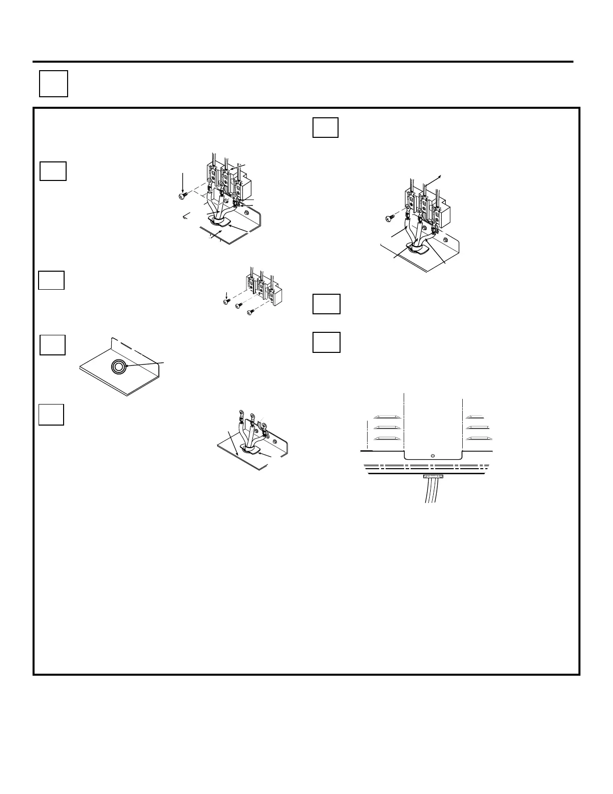
Remove the screws on
the terminal block with a
1/4” nut driver or phillips
screwdriver.
Remove
3 screws
B5a
B6a
Install the three-wire
cord and strain
relief through the
hole in the
connection plate.
THREE- WIRE CORD CONNECTION KIT
7
Knockout in center
of connection plate
may be taken out
B7a
B8a
Connect the outer wires to the outside
terminals and the center wire to the
center terminal. Do not remove the
ground strap
Push the cord upward (to relieve strain),
while tightening the strain relief clamp.
B9a
Re-install the wire cover with the 5
screws removed earlier. Make sure the
wires do not become pinched between
the wire cover and mainback.
Wire
Cover
Special note: If local codes require an
undgrounded neutral, you must do the
following:
a. Remove ground strap.
b. Fasten the white wire to the center terminal.
c. Use grounding terminal or lead to ground unit
in accordance with local codes.
3
Screws
Grounded
Neutral
Terminal
(White)
Ground Strap
Ground Screw
Strain
Relief
Clamp
Connection
Plate
Center
Wire
Connection
Plate
Strain
Relief
Clamp
3 wire
cord kit
Outer
Wire
Center
Wire
Outer
Wire
Grounded
Neutral
Terminal
(White)
 Loading...