Cooling Air Flow
Air enters the door assembly through large slots in the bottom and flows
upward between the inner and outer assemblies, exhausting through slots in
the top of the door. DO NOT INSULATE THIS AIR CHANNEL.
To Service Full Glass Door
1. Complete door assembly:
• Remove three screws from the bottom door frame
• Remove two screws at the top of the door on the liner
• The liner assembly and outer glass panel assembly can now be separated.
2. Outer glass panel assembly:
• Remove four screws from the side posts at the bottom
• Remove four screws from the side posts at the top near the door vent trim
• Slide the bottom trim and top vent trim out to free the outer door glass
Note: On some doors the bottom trim is sealed to the outer door glass and
cannot be separated.
3. Liner assembly:
• Remove three screws on each side of the door liner to remove the door
hinge assembly
• Remove four screws from the insulation retainer
• Remove insulation retainer and then the insulation
• The window pack and window gasket are now accessible,
on units with a window door.
Door Gasket
The door gasket is clipped into the liner of the
door panel.
To Service Gasket
A gap must be left in the gasket at bottom of door.
The gap is required to provide air flow in the oven for proper baking results.
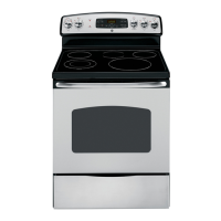
30" RADIANT FREE-STANDING SELF-CLEAN
ELECTRIC RANGE
TEMPERATURE LIMIT/HOT LIGHT SWITCH
The Temperature Limit/Hot Light Switch performs two functions:
1.
Turns on HOT LIGHT
when the glass surface above the heating unit has
reached 150°F. The hot light will remain on until the glass surface above the
heating unit has cooled below 150°F (even after surface unit switch has been
turned off).
2. Detects when glass temperature above a unit has exceeded its limit of
approximately 1031°F and disconnects power to that unit. When glass
temperature cools below 1031°F, the unit will turn back on. The temperature
limit/hot light switch cannot be calibrated.
CONTROL PANEL REMOVAL
The control panel contains the ERC infinite heat switches.
To Service:
1. Remove 2 screws (from bottom) securing control panel to the backguard.
2. Remove 4 screws at the top, in the back of the range.
3. Pull bottom of panel out while lifting panel up.
4. Lay panel on cooking surface.
CAUTION: Place protective covering (such as towel) between control panel and
cooking surface to avoid damage to control panel.
COOKTOP REMOVAL
The cooktop is fastened to the front frame by two screws.
Remove the screws and lift the back edge of cooktop
upward (no more than 1 to 2 inches) to unhook the
cooktop hinge from the backguard pins. Pull forward.
Unplug harness and unscrew ground wire located at rear
of cooktop. Lift cooktop off.
NOTE: Raising cooktop too high can break the glass.
T09 CONTROL
The Electronic Range Control system consists of the control, key panel, oven
sensor, door lock assembly.
Key Panel Test
Depress each pad on the Key panel. If the Key panel is functioning properly the
following should occur:
• Bake, Broil, Convection Bake, Self Clean, Kitchen Timer, Cooking Time, Start
Time–Audible tone plus display showing mode of operation selected.
• Start/On, Clear/Off–Audible tone and display shows time of day.
•
Increase/Decrease pads–No audible tone. Can only be used after another
function has been selected. Pressing both keys at the same time turns display on/
off.
• Clock - Audible tone and display change..
Sensor & Lock Circuits
Ohmmeter Test
Disconnect power and make
measurement from side of
connector that has terminals exposed.
CONTROL VOLTAGE–ERC
NOTE: Mode and temperature selection is necessary for operation of relay
contacts. This model incorporates Double Line Break meaning there is no
voltage on the elements when the control is in standby.
FAILURE MEANING CORRECTION
CODE
OVEN
OVERTEMPERATURE
CONDITION
• Door unlocked–oven
exceeded ~620°F
• Door locked–oven
exceeded ~930°F
• Door latch unlocked
while oven in excess
of ~620°F
1. If no overtemperature condition occurred–check all
contacts and connections in sensor circuit. Eliminate
excessive resistance in sensor circuit due to increased
contact/connector resistance.
2. If overtemperature condition occurred–look for
welded relay contacts on bake, broil, or double-line-
break relays. If relay contact welding is confirmed–
REPLACE CONTROL.
3. Ensure Door Latch stays locked for duration of CLEAN
cycle.
F2
OPEN OVEN SENSOR
Sensor resistance
>2900 ohms
Disconnect sensor/latch connector from the control.
Measure sensor circuit resistance at sensor/lock switch
connector (should be ~1100 ohms at room temperature).
Ensure each sensor lead to chassis ground resistance is
infinitely high.
If open or short circuit is detected:
1. Look for cut or pinched sensor harness wire.
2. Look for sensor leads shorted to chassis ground.
3. Look for loss of terminal contact in the harness and at
the control.
4. Check sensor resistance directly at sensor harness
connector (away from the control). If reading is
abnormal–REPLACE OVEN SENSOR.
If sensor circuit appears to be normal:
1. Reinstall sensor/lock switch connector on the control
and measure sensor resistance at solder joints on
the back of the control circuit board. If abnormal
resistance reading is observed–RESTORE CONTACT
PRESSURE OR SENSOR/LOCK SWITCH CONNECTOR.
If corrective actions above do not eliminate the
problem–REPLACE CONTROL.
F3
SHORTED OVEN
SENSOR
Sensor resistance
<950 ohms
F4
SHORTED MATRIX
KEY
Power down then power up the range. If the fault condition
reappears within 15 minutes–REPLACE CONTROL.
F7
EEPROM ERROR
Power down then power up the range. If the fault
condition reappears within 5 minutes–REPLACE CONTROL.
F8
T09 FAULT CODES
Fault Code Recall. Press and hold the Time, +, and - keys at the same time to
retrieve the past 3 failure codes. Press and hold the Time and Clock keys at the
same time to clear all fault codes from memory.
REMOVABLE OVEN DOOR
To Remove:
1. Fully open the door.
2.
Push the hinge locks down toward the door frame, to the
unlocked position. This may require a flat blade screwdriver.
3. Firmly grasp both sides of the door at
the top.
4. Close door to the door removal position.
5. Lift door up until the hinge arm is clear
of the slot.
To Replace:
1. Firmly grasp both sides of the door
at the top, with the door at the same
angle as the removal position, seat
the indentation of the hinge arm into
the bottom edge of the hinge slot.
2. Fully open the door.
3. Push the hinge locks up against
the front frame of the oven cavity,
to the locked position.
4. Close the oven door.
Terminals on ERC Voltage, standby Voltage, Broil Voltage, Bake
(element terms (no relays mode active mode active
are on tops energized)
of large relays)
L1-N 120VAC (if not, harness may be bad)
L1-L2 240VAC (if not, harness may be bad)
L1-BAKE 240VAC (mode ~0VAC when bake element
active, bake on (if not, relay/ERC may
relay off, DLB be bad)**
relay on)*
L1-BROIL ~0VAC when 240VAC (mode active, broil
broil element relay off, DLB relay on)*
on (if not,
relay/ERC may
be bad)**
**If not, check indicated element and harnessing.
**Relay is on only when calling for heat. 240VAC when not calling for heat, else check
indicated element and wiring.
~0VAC (if not,
relay may be
bad)
0SYPRT]c2PQX]Tc
>a5X]P[;^RPcX^]
>UAP]VTBXST?P]T[
FP[[
5[^^aF^^S
1aPRZTc
BXST
ATPa
;TeT[X]V
;TV
5[^^a2^]RaTcT
AT\^eP[?^bXcX^]
7X]VT0a\
1^cc^\
4SVT
^UB[^c
8]ST]cPcX^]
3^^a_P]T[
6PbZTc
2^^Zc^_
<^d]cX]VBRaTfb!
7X]VT?X]b
1
2
3
4
5
1100
DOOR LOCK CIR.
PINS 3 & 5
@ RM. TEMP.
2600
@ 865 OVEN
OVEN SENSOR
PINS 1 & 2
C
NC
LOCK SWITCH
DOOR LATCH MECHANISM
The latch mechanism is thermally operated.
When the latch handle is moved to the
clean position the latch hook engages
into a slot in the oven door. As the clean
cycle progresses, the increase in oven
temperature causes a bi-metal spring
on the latch mechanism to expand. This
expansion causes the thermal lock to
move into the path of the latch mechanism
thus locking it into position. The door locks
when the oven has reached a temperature
between 560 and 600 degrees F and will remain locked until the oven has
dropped below these temperatures (560-600 degrees F).
SPECIAL FUNCTION ON T09 CONTROL:
Hold Bake and Broil keys simultaneously for 3 seconds until display shows
SF (Special Function). Select the are to change. When change has been made
press start key to return to time of day.
• Adjust oven temperature: Press Bake key, Display shows ‘OO’. Use Up/Down
keys to change the oven temperature. Oven temperature can be adjusted to a
range of +/-35 degrees in steps of 1 degree.
• SAb/ON/OFF: Press Cook Time key when display showing ‘SF’. The display
changes for every clock key press to ON/OFF/SAb. ON stands for 12 Hr
shutdown, OFF stands for no Shut down, SAb stands for SABBATH special feature.
• Clock Display ON/OFF: Press Timer ON/OFF key to toggle the clock display
on/off while in Standby Mode. NOTE: The control defaults to ON when power is
cycled to the range.
NOTE:
• BAKE/TIME BAKE – Bake and broil elements
cycle during preheat and balance of
operation, one unit is on at a time.
• CLEAN – Broil element only on during 1st 30
minutes or until oven reaches 750°F. During
balance of clean bake and broil elements will
cycle on alternately.
• See schematic for wattage values.
Locked Position
Hinge Lock
(Unlocked Position)
Seated Hinge Arm
Hinge Arm
Slot
DUAL CIRCUIT CONTROL
The right front element and left front element
have two cooking zones:
• To use the large cooking area, push to turn
the control knob clockwise to desired setting.
• To use the small cooking area, push to turn the
control knob counterclockwise to desired setting.
When a cooking zone is activated, coils beneath the
zone radiate heat through the glass cooktop to the
utensil. The red glow of the coils will be visible through
the glass. It will take the cooking zone on the glass
surface a few moments to heat up. The coil cycles on and
off to maintain the selected control setting.
NOTE: Installation
information for
reference only.
See Installation
Instructions shipped
with product for
complete details and
before attempting
to install.
Anti-tip
bracket must be
attached to the floor or wall to hold either right or left rear leveling leg. Make
sure leveling leg re-engages the bracket when range is moved for any reason.
A child or adult can tip the range and be killed.
Verify the anti-tip bracket has been properly installed
and engaged.
Ensure the anti-tip bracket is re-engaged when the range
is moved.
Do not operate the range without the anti-tip bracket in
place and engaged.
Failure to follow these instructions can result in death or
serious burns to children or adults.
Tip-Over Hazard
WARNING
Screw Must Enter
Wood or Metal
Bracket
Wall Plate
Attachment to Wall
or Floor
;^RZ
BfXcRW
1X\TcP[
B_aX]V
0bbT\Q[h
CWTa\P[
;^RZ
;PcRW
;^RZ
B AK E
B AK E
DLB
R Y 102
"L-1"
B L A CK
R Y101
L1-2
B R OI L
B R OI L
"L-2"
RED
B AKE & TIME B AKE/CL E A N
DLB
"L-1"
BLACK
"L-2"
RED
L1
L2
BROIL
BROIL & CLEAN-UNTIL
FIRST CYCLE OFF
RY100
RY102
WARNING
Electrical Shock Hazard
Death or serious injury can result from failure to follow
these instructions.
• Service by a qualified service technician only.
• Disconnect power before servicing this product.
• Reconnect all grounding devices after service.
• Replace all parts and panels before operating.
31-17230