Installation Instructions
Free-Standing Electric Ranges
Questions? Call 1.800.GE.CARES {1.800.432.27371 or visit www.GEAppliances.com
In Canada, call 1.800.561.3344 or visit www.GEAppliances.ca
BEFORE YOU BEGIN
Readthese instructions campletely and
carefully.
" IM PO RTANT -- Save these instructions
for local inspector's use.
" IMPORTANT -- Observeall
governingcodesand ordinances,
, NotetoInstaller- Besureto leavethese
instructionswithconsumer.
, Note to consumer - Keep these
instructions for future reference.
, Skill level - Installation of this appliance
requires a qualified installer or electrician.
Proper installation is the responsibility of the
installer.
Product failure due to improper installation is
not covered under warranty.
FOR YOUR SAFETY:
! A D
TLo-Over Hazard
A child or adult can tip the range and be killed.
Install the anti-tip bracket to the wall or floor.
Engage the range to the anti-tip bracket by sliding the
range back such that the foot is engaged.
Re-engage the anti-tip bracket if the range is moved.
Failure to do so can result in death or serious burns
to children or adults.
If you did not receive an anti-tip bracket with your purchase,
call !.800.626.8774 to receive one at no cost. (In Canada,
call &.800.B61.3344.)For installation instructions of the bracket,
visit: www.GEAppliances.com (In Canada, www.GEAppliances.ca.)
Anti-Tip Bracket
Kit Included
_WARNING -- Beforebeginning
the installation,switch poweroffat service
panelandlockthe servicedisconnecting
meansto preventpowerfrombeing
switchedanaccidentally.Whenthe service
disconnectingmeanscannot be locked,
securelyfastena prominentwarning device,
such asa tag,to the service panel.
MATERIALS YOU MAY NEED
@
Squeeze Connector (ULListed40 AMP)
(ForConduit 4-Wire Cord 4' long OR
Installations Only) 3-Wire Cord 4' long
TOOLS YOU WILL NEED
Drillwith1/8"Bit TinSnips
SafetyGlosses Tape Measure
Adjustable Wrench Pliers
Level 1/4" Nut Driver
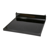
| REMOVE PACKAGI NG MATERIALS: Failure to remove packaging materials could
result in damage to the appliance. Remove all packing parts from oven, racks, heating elements
and drawer. Also, remove protective film and labels on the outer door, cooktop and control panel.
_-I PREPARE THE OPENING (FOR INDOOR USE ONLY)
See illustrations for all rough-in and spacing dimensions. The range may be placed with 0"
clearance (flush) at the back wall and side walls of the cabinet.
SINGLE OVEN DOUBLE OVEN
On models with baking
or warming drawers,
electrical outlet must not _ ---_ 23_" .,, :
be in this area. i 7_3¼"
Acceptabie electricaloutlet area. \.._ 45" //
./
Orient electrical receptacleso the ......."
lengthis parallel to floor. " ......................
* GE-brandedmodels have control
panels30Ud' wide.
NOTE: Use a 4' power cord to prevent interference
with the storage drawer. Power cords 4_' to 6' long
may hove to be dressed to allow for proper drawer
closing.
MINIMUM DIMENSIONS BETWEEN COOKTOP,
WALLS AND ABOVE THE COOKTOP:
A. Make sure the wall covering, countertop, flooring
and cabinets around the range can withstand the
heat (up to 200°F) generated by the range.
B. Allow 30" minimum clearance between surface
units and bottom of unprotected wood or metal
cabinet, or allow a 24" minimum when bottom
of wood or metal cabinet is protected by no less
than 1/4" thick flame retardont millboord covered
with not less than No 28 MSG sheet metal, (.015"),
.015" thick stainless steel, .024"
aluminum or .020" copper.
NOTEC
iL
B
C
Both
Sides
i
i
i
i
i
C. This appliance has been approved for 0" spacing to adjacent surfaces above the cooktop. However,
a 6" minimum spacing to surfaces less than lS" above the cooktop and adjacent
cabinet is recommended to reduce exposure to steam, grease splatter and heat.
To reduce the risk of burns or fire when reaching over hot surface elements, cabinet storage space
above the cooktop should be avoided. If cabinet storage space is to be provided above
the cooktop, the risk can be reduced by installing a range hood that projects at least 5" beyond
the front of the cabinets. Cabinets installed above the cooktop must be no deeper than 13".
r_ ELECTRICALREQUIREMENTS
A WARNING: This appliance must be properly grounded.
J_, WAR NIN G: All new constructions, mobile homes, recreational vehicles and installations where
local codes do not allow grounding through neutral, require a 4-conductor UL-listed range cord.
A WARN IN G: To prevent fire or shock, do not use an extension cord with this appliance.
_1_WARN IN G: To prevent shock, remove house fuse or open circuit breaker before
beginning installation.
We recommend you have the electrical wiring and hookup of your range connected by a qualified
electrician. After installation, have the electrician show you how to disconnect power from the range.
You must use a single-phase, 120/208 VAC or 120/240 VAC, 60 hertz electrical system. If you connect
to aluminum wiring, properly installed connectors approved for use with aluminum wiring must be
used.
Effective January 1, 1996, the National Electrical Code requires that new construction (not
existing) utilize a 4-conductor connection to an electric range. When installing an electric range
in new construction, mobile home, recreational vehicle, or an area where local codes prohibit
grounding through the neutral conductor, refer to the section on four-conductor branch circuit
connections.
Check with your local utilities for electrical codes which apply in your area. Failure to wire your oven
according to governing codes could result in a hazardous condition. If there are no local codes, your
oven must be wired and fused to meet the National Electrical Code, NFPA No.
70 i latest edition, available from the National Fire Protection Association.
This appliance must be supplied with the proper voltage and frequency, and connected to an
individual, properly grounded, 40 amp (minimum) branch circuit protected by a circuit breaker
or time-delay fuse.
Use only a S-conductor or a 4-conductor UL-listed range cord. These cords may be provided with ring
terminals on wire and a strain relief device.
A range cord rated at 40 amps with 125/250 minimum volt range is required. A 50 amp range cord
is not recommended but if used, it should be marked for use with nominal 1_ diameter connection
openings. Care should be taken to center the cable and strain relief within the
knockout hole to keep the edge from damaging the cable.
The rating plate is located on the oven frame or on the side of the drawer frame.
Rating plate
SINGLE OVEN DOUBLE OVEN
Rating
| POWER CORD AND CONDUIT INSTALLATION
r_ Remove wire cover (on the back of range) by removing screws using a 1/4" nut driver. You carl
access the terminal block by either removing a terminal block cover (on some models) or the
wire cover. Do not discard these screws.
Back of range Back of range
5 screws to
cover
Wire cover
For power cordand 1" conduit only, remove the
knockout ring (1%")located on bracket directly
below the terminal block. To remove the
knockout, use a pair of pliers to bend the
knockout ring away from the bracket and
twist until ring is removed.
Terminal block
(appearance
may vary)
Knockout
ring in
bracket.
[
Knockoutring ___
removed
Fa
Screw to
remove
terminal
block cover
Terminal block cover
For power cord installations only
(seethe next step if using conduit),
assemble the strain relief in the hole. Insert
the power cord through the strain relief
and tighten. Allow enough slack
to easily attach the cord terminals to
the terminal block. Iftabs are present at
the end of the winged strain relief, they
can be removed for better fit.
NOTE:Do not installthe power cord without a
strain relief.Thestrain relief bracketMUSTbe
installed before
reinstallingthe rear rangewiring cover.
r61For 3/4" conduit installations only, purchase a squeeze connector matching the diameter
ofyour conduit and assemble it in the hole. Insert the conduit through the squeeze connector
and tighten. Allow enough slackto easily attach the wires to the terminal block. NOTE:Do not install the
conduit without a squeeze connector. The squeeze connector MUSTbe installed before reinstalling
the rear range wiring cover.
Squeeze _i_-_ _l
CONNeCtor
_LL\_ " i i Terminal block
Conduit _L_ ------_--'- Bracket
Proceed to step 5 or 6.
r_ 3-WIRE INSTALLATION
A WARN ING: The neutral or ground wire of the power cord must be connected
to the neutral terminal located in the center ofthe terminal block and the ground strap must connect the
neutral terminal to the ground plate. The power leads must be connected to the lower left and the lower right
terminals of the terminal block.
DO NOT remove the ground strap connection.
FOR POWER CORD INSTALLATION
A. Remove the 3 lower terminal screws from the terminal block.
B. Insert the 3 terminal screws through each power cord terminal ring and into the lower
terminals of the terminal block. Be certain that the center wire (white/neutral)
is connected to the center lower position of the terminal block.
C.Tighten screws securely into the terminal block.
FOR CONDUIT INSTALLATION
A. Loosen the 3 lower terminal screws on the terminal block. Strip wire to exposed tip about 5/8" long.
B. Insert the center (white/neutral) wire tip through the bottom center terminal block opening.
On certain models, the wire will need to be inserted through the ground strap opening
and then into the bottom center block opening. Insert the two side bore wire tips into
the lower left and the lower right terminal block openings.
C.Tighten the screws until the wire is firmly secured (35to 50 inch-lbs.).Do not over-tighten
the screws.
NOTE: ALUMINUM WIRING: Aluminum building wire may be used butit must be rated
for the correct amperage and voltage.
Power Cord
Terminal block
(appearance
may vary)
Neutral terminal
Ground strap
Ground
plate
Conduit
Terminal ------__
Power cord _
PROCEED TO STEP 7.
31-108!6
08-11 GE
[]_] 4-WIRE INSTALLATION
A WAR NI NG: The neutral wire of the supply circuitmust be connected to the neutral terminal
located in the lower center of the terminal block.The power leadsmust be connected tothe lower left and the
lower right terminals ofthe terminal block.Thegrounding lead must be connected tothe frame of the range with
the ground plate and the green ground screw.
FOR POWER CORD INSTALLATION
A. Remove the 3 lower terminal screws from the terminal block. Remove the ground screw and ground
plate and retain them. Cutand discardthe ground strap.DONOTDISCARDANYSCREWS.
B. Insertthe one ground screw into the power cord ground wire terminal ring,through the ground plate
and intothe frame of the range.
C. Insertthe 3 terminalscrews(removedearlier)through each power cord terminal ringand into the lower
terminals ofthe terminal block.Becertain that thecenter wire (white/neutral)isconnected to the center lower
positionofthe terminal block Tightenscrewssecurelyinto theterminal block.
FOR CONDUIT INSTALLATION
A. Loosen the 3 lower terminal screws on the terminal block. Removethe ground screw and ground plate and
retain them. Cut and discord the ground strap. DO NOT DISCARDANYSCREWS.Strip wire to exposed tip
about 5/8" long.
B. Insertthe ground bare wire tip between the range frame and the ground plate (removed earlier)
and secure itin placewith the ground screw (removedearlier). Insertthe bare wire (white/neutral) tip through
the bottom center of the terminal block opening.Insert the two side bare wire tips into the lower left and the
lower right terminal block openings.
C.Tighten the screws until the wire is firmly secured (35to 50 inch-lbs.).Do not over-tighten the screws.
NOTE: ALUMINUM WIRING: Aluminum building wire may be used but it must be rated
for the correct amperage and voltage.
Before-Power Cord and Conduit
Ground _ _ \-,
strap Neutral
terminal
After-Power Cord
Terminal _
block (_
Ground _i
screw
2" ' ,7_'_ _ Neutral
terminal
Ground plate
F groundin to
range)
After-Conduit
Terminal -----__
block
Wire --"-"_ /,"_
tips i_._
Ground screw t_
_ round
plate
(grounding
_ torange)
REPLACE THE WIRE COVER
Replace wire cover on range back by sliding its left edge under the retaining tabs and replace the
screws removed earlier. Make surethat no wires are pinched between cover and range back.
Back of range Back of range
_5 screws to
remove wire
cover
Screw to
remove
terminal
block cover
-- ......... _ Terminal
_ block cover
r_ ANTI-TIP DEVICE INSTALLATION
Ti -Over Hazard
• A child or adult ca ntip the range and be killed.
• Install the anti-tip bracket to the wall or floor.
• Engage the ra nge to the anti-tip bracket by sliding the
range back such that the foot is engaged.
• Re-engage the anti-tip bracket if the range is moved.
• Failure to do so can result in death or serious burns
to children or adults.
To reduce the risk of tipping the range, the
range must be secured by a properly installed
anti-tip bracket. See installation instructions
shipped with the bracket for complete details
before attempting to install.
Tocheck if the bracket is installed and
engaged properly, look underneath the range
to see that the rear leveling leg is engaged
in the bracket. On some models, the storage
drawer or kick panel can be removed for
easier inspection. If visual inspection isnot
possible, slide the range forward, confirm the anti-tip bracket is securely attached to the floor or wall, and
slide the range back so the leveling leg is under the anti-tip bracket. If the range is pulled from the wall for
any reason, always repeat this procedure to verify the range is properly secured by the anti-tip bracket
Never completely remove the leveling legs or the range will not be secured to the anti-tip bracket.
F_LEVELTHE RANGE
A WARN ING: Never completely remove the leveling leg
as the range will not be secured to the anti-tip device properly.
MODELS WITH STORAGEDRAWEROR KICK PANELS
B3
@
B3
rsq
Plug in unit and slide into place. Pull drawer out until it stops.
Lift front of drawer until the stops clear the guide. Remove the drawer.
Install the oven shelves in the oven and position the range where
it will be installed.
Check for levelness by placing a spirit level on one of the oven shelves. Spirit level
Take two readings-with the level placed diagonally first
in one direction and then the other.
r_ The front leveling legs can be adjusted from the bottom
and the rear legs can be adjusted from the top or the bottom.
r_ Use an adjustable wrench to adjust the leveling legs until
the range is level.
[_1 LEVEL THE RANGE (CONT.)
r_ Position cord so that it does not interfere with drawer.
Place drawer rail on guides. Push the drawer in until it stops.
r_ Lift front of drawer and push in until the stops clear
the guides.
D Lower the front of the drawer and push in until it closes.
MODELSWITHBAKING,WARMINGDRAWERSORDOUBLEOVEN
r_ Plug in the unit.
r_ Measure the height of your countertop atthe rear of the opening (X).
r_ Adjust two rear leveling legs so that the rear of cooktop is at the same height
as the counter (Y).
r_ Slide unit into place.
r_l install oven shelves in the oven and position the range where it will be installed.
r_ Check for levelness by placing a spirit level on one of the oven shelves.
Take two readings-with the level placed diagonally first in one direction
and then the other.
r_ Adjust front leveling legs until the range is level.
e
range
iY
FINAL INSTALLATION CHECKLIST
,,Check to make sure the circuit breaker is closed (RESET)ar the circuit fuses are replaced.
Be sure power is in service to the building.
Checkthat all packing materials and tape have been removed. This will include tape on metal panel under
control knobs (if applicable), adhesive tape, wire ties, cardboard and protective plastic. Failure to remove
these materials could result in damage to the appliance once the appliance has been turned an and
surfaces have heated.
Checkthat the door and drawer are parallel to each other and that both operate smoothly. If they
do not, see the Owner's Manual for proper replacement.
Checkto make sure that the rear leveling leg isfully inserted into the Anti-Tip bracket and that the bracket
issecurely installed.
OPERATION CHECKLIST
Turn on one of the surface units to observe that the element glows within 60 seconds. Turnthe unit
aff when glow is detected. If the glow is not detected within the time limit, recheck the range wiring
connections. If change is required, retest again. If no change is required, have building wiring checked for
proper connections and voltage.
Checkthat the Clock (on models so equipped) display is energized. If a series of horizontal red
lines appear in the display, disconnect power immediately. Recheckthe range wiring connections.
If change is made to connections, retest again. If no change is required, have building wiring checked for
proper connections and voltage. It is recommended that the clock be changed if the red lines appear.
Be sure all range controls are in the OFFposition before leaving the range.