Do you have a question about the GE JKP16G0J3BG and is the answer not in the manual?
Connect range to proper voltage/frequency circuit. Wire size must conform to code. U.L. approved leads have higher temp rating than household wiring.
Details on NEC rating for ranges and wall ovens/cooktops based on voltage and appliance type.
Specifies maximum ground path resistance and minimum insulation resistance for proper grounding.
Procedure to test and calibrate surface unit switches using percent-on time measurements.
Covers tilt-lock units, leveling, stripped screw holes, and lead connections for proper function.
Explains air entry, flow path between panels, and exhaust for oven doors. Do not insulate air channels.
Steps to remove and replace the door handle and barrier assembly from the oven door.
Procedure to replace the black glass panel by removing trim and liner components.
Instructions for adjusting and replacing the door gasket, including checks for proper seal.
Procedure for adjusting door seal and alignment by loosening hinge support screws.
Methods to adjust door balance and broil stop retention force for smooth operation.
Solution for a door that is loose in the broil position using hinge shims.
Specifies temperature limits, optimum range, and amplitude for bake and clean settings.
Instructions for adjusting thermostat calibration using an oven tester and thermocouple.
Guidance on clean calibration, acceptable cleaning, and diagnosing issues via soil patterns.
Schematic diagram illustrating the electrical connections for the lower oven.
Details current and voltage for Bake, Timed Bake, and Broil oven switch positions.
Identifies components of the self-clean latch mechanism like solenoid, spring, and pawl.
Schematic diagram for the self-clean cycle, including timer, fan, and solenoid.
Explains the micro switch operation for latch solenoid control during self-cleaning.
Wiring diagrams for Bake, Time Bake, and Broil-Rotisserie functions.
Information on the smoke eliminator's construction, replacement parts, and service procedure.
Exploded view of the oven's control panel and associated components.
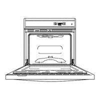
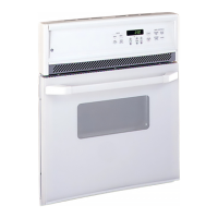
Exploded view of the oven door, showing inner and outer panel parts.
Diagrams and details of the oven selector switch, dual-range thermostat, and thermal switch.
Comprehensive wiring schematic for the self-clean oven, showing various circuits and components.
Information on multiple resistors, probe receptacle, and their resistance tolerances.
Schéma électrique détaillé pour le four autonettoyant, incluant le sélecteur de four et le thermostat.
Détails sur les résistances multiples, le transformateur, et les tolérances de résistance.
| Brand | GE |
|---|---|
| Model | JKP16G0J3BG |
| Oven Type | Single |
| Fuel Type | Electric |
| Color | Black |
| Oven Cleaning Type | Self-Clean |
| Interior Lighting | Yes |
| Number of Oven Racks | 2 |
| Oven Rack Positions | 4 |
| Broil Element Power | 3, 000 Watts |
| Bake Element Power | 2, 500 Watts |
| Oven Cleaning | Self-Clean |
| Weight | 150 lbs |