EasyManua.ls Logo

GE JungleMUX 86445-31 - User Manual

GE JungleMUX 86445-31
95 pages
Print Icon
To Next Page IconTo Next Page
Loading...
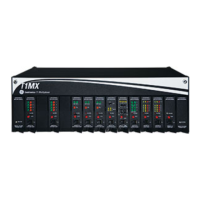
JungleMUX
SONET Multiplexer
86445 2W FXS/PLAR UNIT
3
3
4
4
2
2
-
-
8
8
6
6
4
4
0
0
0
0
-
-
4
4
4
4
5
5
P
P
S
S
I
I
s
s
s
s
u
u
e
e
4
4
.
.
0
0
O
O
c
c
t
t
o
o
b
b
e
e
r
r
2
2
0
0
0
0
6
6
Technical Practice
and
Installation Manual
Copyright © GE Multilin Inc. 2002

Table of Contents

Questions and Answers

  • L
    Lisa SmithAug 14, 2025
    What to do if signaling is not functioning correctly on GE JungleMUX 86445-31?
    • R
      Ryan BrownAug 14, 2025
      If the signaling is not functioning correctly on your GE Multiplexer, ensure that the proper signaling type is selected at both ends. Also, ensure that neither signaling direction is in test, meaning both Transmit Signaling and Receive Signaling fields in Test Setup window are set to '-' at both ends (or, if JCI is used, both Transmit Signaling and Receive Signaling fields in Signalling Setup window are set to 'NRML'). Finally, ensure that the sub-board (028-86445-04) is installed on the unit's main board. Note that the sub-board must be removed if external talk battery and ringing generator are used.
  • S
    Steven MarshallAug 26, 2025
    Why is the red LED on my GE JungleMUX 86445-31?
    • J
      Jeremiah WardAug 26, 2025
      If the red LED is on in GE Multiplexer, verify the unit temperature is not excessive (> 93°C). Also, verify that the sub-board (028-86445-04) is installed or an external battery connection, ringing voltage and ringing control is provided. If the condition persists after the unit is reseated, replace the unit because the internal DC-DC converter may have failed.
  • L
    levyjohnnyNov 3, 2025
    How to troubleshoot no transmission in GE Multiplexer?
    • J
      Jessica StewartNov 3, 2025
      If there is no transmission in either transmit or receive direction with your GE Multiplexer, make sure that JIF/JIF-Share units or JMUX units are not in alarm and the VT/DS0 channel path is correct. Also, verify that VT dropped at JMUX unit(s) is correct and check TSI/CC configuration (if applicable). You should also verify that VT assigned at JIF/JIF-Share unit(s) is correct. If a shared VT is used, verify the correct DS0 channels are dropped at JIF-Share unit(s). Verify that the unit is physically connected to the proper JVT port and ensure that Add and Drop configuration at both ends is correct per the Node Assignment Drawing. Verify that local and remote unit configuration is correct, as well as local and remote unit channel numbers and signaling type selections are matching. Check Tr...

Summary

PART 1: 86445-31 2 W FXS;PLAR Unit (Single-Channel)

1.1 INTRODUCTION

Introduces the 86445-31 2W FXS/PLAR unit and its application in the utility industry.

1.2 UNIT OVERVIEW

Describes the unit's capabilities, configuration modes, impedance, LEDs, and connections.

1.3 FRONT PANEL FEATURES

Details LED indicators, Bantam Jack, Push-button (ACK), and Craft Interface (CI) Jack.

1.4 UNIT DESCRIPTION

Explains the main and subassembly boards, SLIC, CODEC, PLGA, and signal paths.

1.5 INSTALLATION

Provides instructions for installing the 86445-31 FXS unit, including pre-installation and strapping options.

1.6 CONFIGURATION

Details how to configure the 86445-31 unit using VistaNET or JCI software.

1.7 MAINTENANCE and TROUBLESHOOTING

Covers maintenance procedures and troubleshooting steps for the unit.

1.8 UNIT PARAMETERS

Lists and explains the voice frequency and signaling parameters of the unit.

1.9 SPECIFICATIONS

Outlines the physical, electrical, environmental, mechanical, EMI/RFI, isolation, and reliability specifications.

1.10 ORDERING INFORMATION

Provides information on ordering the 86445-31 unit and associated paddleboard assembly.

PART 2: 86445-32 2 W FXS;PLAR Unit (Dual-Channel)

2.1 INTRODUCTION

Introduces the 86445-32 2W FXS (dual-channel) unit and its applications.

2.2 UNIT OVERVIEW

Describes the dual-channel unit's features, configuration modes, and settings.

2.3 FRONT PANEL FEATURES

Details LED indicators, Bantam Jacks, and the Push-button (ACK) for the dual-channel unit.

2.4 UNIT DESCRIPTION

Explains the architecture and components of the 86445-32 unit.

2.5 INSTALLATION

Provides instructions for installing the 86445-32 FXS unit.

2.6 CONFIGURATION

Details how to configure the 86445-32 unit using VistaNET software.

2.7 MAINTENANCE and TROUBLESHOOTING

Covers maintenance and troubleshooting for the dual-channel unit.

2.8 UNIT PARAMETERS

Lists and explains voice frequency parameters for the dual-channel unit.

2.9 SPECIFICATIONS

Outlines the physical, electrical, environmental, mechanical, EMI/RFI, and isolation specs.

2.10 ORDERING INFORMATION

Provides ordering information for the 86445-32 unit and paddleboard.

APPENDIX A

TLP SETTINGS

Explains the importance of Transmission Level Point settings for end-to-end voice performance.

APPENDIX B

JCI SCREEN INFORMATION FOR 86445-31 UNIT

Provides information on the JCI screen for the 86445-31 unit.

APPENDIX C

LIST OF ILLUSTRATIONS

Lists all figures included in the manual.

APPENDIX D

LIST OF ACRONYMS

Lists and defines acronyms used throughout the document.

GE JungleMUX 86445-31 Specifications

General IconGeneral
Power Supply-48 VDC
Input Impedance75 Ohms (coaxial), 120 Ohms (balanced)
Output Impedance75 Ohms (coaxial), 120 Ohms (balanced)
Operating Temperature Range-40°C to +70°C
Dimensions19" rack mountable, 1U height
Weight8 lbs (3.63 kg)

Related product manuals