16 49-80783-3
2
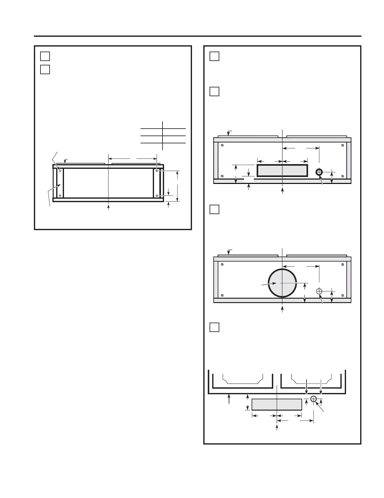
PREPARING MOUNTING (Cont)
B
To install to the bottom of cabinet
Use the diagram or hood as a template and
mark the locations on the cabinet for the
keyholes screws.
Drive the 4 (F) screws partway into the bottom
of the cabinet (or wood shims).
INSTALLATION PREPARATION
Installation Preparation
3
PREPARE FOR ELECTRICAL
AND VENTING
Select the vent option that your installation will
require and proceed to that section:
A
Outside top exhaust
(Vertical duct–3
1
»4” x 10” Rectangular)
• Use the diagram as a template and mark the
locations on the cabinet for ductwork and
electrical wiring.
B
Outside top exhaust
(Vertical duct–7” Round)
• Use the diagram as a template and mark the
locations on the cabinet for ductwork and
electrical wiring.
C
Outside rear exhaust
(Horizontal duct–3
1
»4” x 10” Rectangular)
• Use the diagram as a template and mark the
locations on the cabinet for ductwork and
electrical wiring.
Center line
Electrical access
hole (in cabinet
bottom)
Cabinet front
Cabinet Bottom
Vertical duct
access hole
5
1
»4” 5
1
»4”
7
1
»2”
ø1
1
»4”
4”
1
»2”
3
»4”
Center line
Electrical access
hole (in cabinet
bottom)
Cabinet front
Cabinet Bottom
7
1
»2”
ø1
1
»4”
3
»4”
Access
hole for 7”
round duct
8” DIA.
HOLE
4
1
»4”
Center line
Electrical access
hole (in wall)
Cabinet Front
Cabinet
Bottom
7
1
»2”
ø1
1
»4”
3
»4”
5
1
»4” 5
1
»4”
3
»4”
4
1
»4”
Wood shims
(recessed-bottom
cabinets only)
Center
line
Cabinet Bottom
Cabinet front
2
1
»2”
10
1
»4”
X
Hood mounting screws (4)
Cabinet X
24” 10
3
»4”
30” 13
3
»4”
36” 16
3
»4”