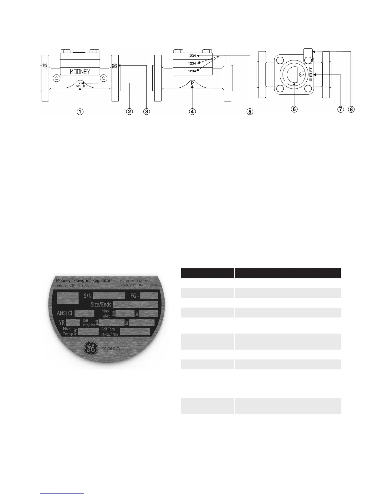
Front View
Back View
Top View
Mooney Flowgrid Regulator Instruction Manual | 3© 2015 General Electric Company. All rights reserved.
Regulator Markings
Nameplate Information
1. American National Standards Institute (ANSI) pressure class rating of the regulator.
2. Line size of body.
3. ANSI pressure class rating of the flange.
4. Indication that the regulator has been hydrostatically tested according to code requirements.
5. The serial number is stamped on the spring case, spacer
1
, and body.
6. The Nameplate location.
7. The flow direction is marked on the spring case (“INLET” or “OUTLET”). Proper alignment assures that the diaphragm
guide on the Spring Case is aligned toward outlet side of the regulator.
8. The % Capacity tag indicates the capacity of the throttle plate (100%, 75%, 50%, & 35%) in the regulator.
1
NOTE: On all 1” regulators and 2” standard regulators the throttle plate itself is stamped.
Item Definition
Flowgrid
Registered name of regulator
Blank
CE marking
S/N
Serial number assigned to regulator
FG
Flowgrid model description
Size/Ends
Line size of body and type of end
connection
ANSI Cl
American National Standards Institute
pressure class
Max Inlet
Maximum inlet pressure (psig)/(bar)
YR
Year manufactured
Diff
Min/Max
Minimum differential required to fully
open regulator
Maximum allowable operating pressure
differential (psig)/(bar)
Max Temp
Maximum operating temperature in
degrees Fahrenheit
Bolt Torq
Ft-lbs/Nm
Recommended bolt torque for spring
case in foot pounds
Figure 2 - Regulator Markings
Figure 3 - Flowgrid Regulator Nameplate
Table 3