© 2016 General Electric All Rights Reserved
1
WARNING: Hazard of electrical shock or burn. Turn off
power supplying this equipment before working inside
General
To comply with the National Electrical Code and
Underwriters Laboratories, the breaker retainer kit and
service barrier must be installed in accordance with the
information contained in this sheet and by a qualified
electrical contractor and/or licensed electrician.
Introduction
This bulletin provides instructions for installing circuit breaker
retainer and Service barrier to Model 6 PowerMark Gold
TM
GE
Load centers. The retainer is used to secure a 2-pole branch
breaker on the load center interior when the breaker is used
as a back-fed main circuit breaker. And Service barriers are
installed on the line side of the breaker.
Contents per Installation
THQLRK4 - Main Breaker Retainer & Service Barrier Kit
NOTICE: These instructions do not purport to cover all
details or variations in equipment or to provide for every
possible contingency to be met in connection with the
installation, operation or maintenance. Should further
information be desired or should particular problems arise
which are not covered sufficiently for the purposes, the
matter should be referred to the General Electric Company.
These instructions are intended for use by qualified
personnel only.
Installation Instructions
1. Uninstall the Dead front/shield and retain the
mounting screws.
2. Install the 2-pole back-fed main circuit breaker (D) in
position 2-4 or 1-3 only. See the load center directory
label or numbers stamped on the dead front/shield to
locate position.
Use only a General Electric type THQL or THHQL two-
pole circuit breaker.
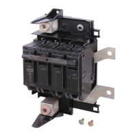
3. Insert the Service Barriers (A) onto line side of circuit
breaker (D) as shown in Figure 1. Two Service Barriers
included with the kit, need to assemble to both the
poles.
Figure 1: Insert Service Barrier onto Main Circuit Breaker
4. Install the retainer (F), over existing nuts (E), and
secure with the 2 nuts (G) provided with the kit.
Tighten to 35 lb-in (4Nm). See figure 2
PowerMark Gold ™
Load Centers
PowerMark Gold
TM
Model 6 Breaker Retainer & Service Barrier Kit Cat# THQLRK4
DEH41481 Installation Instructions