3
List of Illustrations
Figure Page
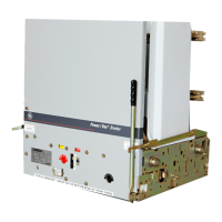
1 Front view of PowerVac
®
breaker with front cover ................... 6
2 Rating interference plate........................................................... 6
3 Front view of PowerVac breaker without front cover ................ 8
4 Manual charging........................................................................ 9
5 Gag plate installation .................................................................10
6 Operating rod assembly ............................................................10
7 Contact gap...............................................................................11
8 Breaker turned on right side......................................................11
9 Close coil plunger gap ...............................................................12
10 Trip coil plunger gap..................................................................12
11 Control switches .......................................................................13
12 Sample operating speed graphs................................................19
13 Contact gap adjustment ............................................................20
14 Auxiliary switch position ............................................................22
15 Spring discharge interlock .........................................................24
16 Toggle linkage positions of the ML-18 mechanism ...................25
17 Schematic of ML-18 mechanism...............................................27
18 Typical wiring diagram for ML-18 mechanism...........................29
19 PowerVac
®
breaker left-front view ............................................30
20 PowerVac
®
breaker right-rear view ...........................................30
21 Trip coil and linkage...................................................................31
22 Close coil linkage.......................................................................32
23 Bottom view of the ML-18 mechanism.....................................33
24 Flex cable connections..............................................................34
25 Negative interlock .....................................................................34
26 Close latch stop.........................................................................35
27 Wipe spring...............................................................................35
Table Page
1 Control Device and Voltage..................................................... 18
2 Measurements ....................................................................... 36
3 Adjustments............................................................................ 36
THESE INSTRUCTIONS ARE INTENDED FOR USE BY QUALIFIED PERSONNEL FOR INSTRUCTION AND MAINTENANCE PURPOSES.
REPRODUCTION IN WHOLE OR IN PART IS NOT PERMITTED WITHOUT THE EXPRESS PERMISSION OF GENERAL ELECTRIC.

 Loading...


