Listed by
Underwriters
Laboratories
* ADA qualified based
on Uniform Federal
Accessibility Standards
For answers to your Monogram
®
or GE appliance
questions, visit our website at geappliances.com
or call GE Answer Center
®
service, 800.626.2000.
C
L
Suitable
bracing
to support
runners
(must support 200 lbs.)
2 x 4 or
equivalent runners
level with bottom of cutout
and flush with sides of cutout
or solid bottom floor.
F
E
22
"
Conduit
40"
D
Cutout depth
23-1/2" MIN
Cabinet 30"
A – Overlap of oven at top of cutout 1"
B – Overlap of oven over side of edges of cutout 3/4"
C – Overlap of oven at bottom of cutout 1-1/4"
Oven
D – Overall depth with handle 27-3/16"
E – Overall height with trim 28-3/8"
F – Overall width 29-3/4"
PT7050
JT5000
JT3000
JT1000
B
30''
A
C
Cutout width
28-1/2" MIN.
28-5/8" MAX.
Recommended
cutout location
from floor
32-1/2"
Cutout height
27-1/4" MIN.
27-5/16" MAX.
23" minimum
door opening
allowance
22" to
bottom of
junction box
Junction box
location
9-1/2"
MAX.
C
L
Suitable
bracing
to support
runners
(must support 200 lbs.)
2 x 4 or
equivalent runners
level with bottom of cutout
and flush with sides of cutout
or solid bottom floor.
F
E
22
"
Conduit
40"
D
Cutout depth
23-1/2" MIN
Cabinet 30"
A – Overlap of oven at top of cutout 1"
B – Overlap of oven over side of edges of cutout 3/4"
C – Overlap of oven at bottom of cutout 1-1/4"
Oven
D – Overall depth with handle 27-3/16"
E – Overall height with trim 28-3/8"
F – Overall width 29-3/4"
PT7050
JT5000
JT3000
JT1000
B
30''
A
C
Cutout width
28-1/2" MIN.
28-5/8" MAX.
Recommended
cutout location
from floor
32-1/2"
Cutout height
27-1/4" MIN.
27-5/16" MAX.
23" minimum
door opening
allowance
22" to
bottom of
junction box
Junction box
location
9-1/2"
MAX.
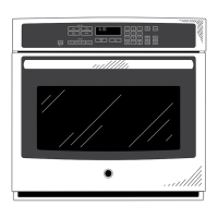
Dimensions and Installation Information (in inches)
Most 30” Wall Cabinets can be used with
this unit.
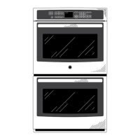
Note: These ovens are not approved
for stackable installations. Cabinets
installed adjacent to wall ovens must
have an adhesion spec of at least a 194°F
temperature rating.
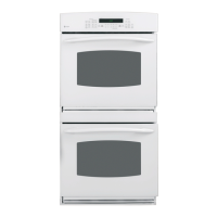
Door handle protrudes 3" from door face.
Cabinets and drawers on adjacent 45°
and 90° walls should be placed to avoid
interference with the handle.
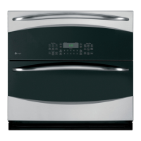
Electric wall ovens are not approved for
installation with a plug and receptacle.
They must be hard wired in accordance
with installation instructions.
Installation Information: Before installing,
consult installation instructions packed with
product for current dimensional data.
Side-by-side installations require at least 2"
between cutouts.
KW Rating
240V
4.5
208V
3.4
Breaker Size
240V
20 Amps
208V
20 Amps
PT7050
Specification Revised 4/13
220252
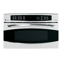
PT7050SF
GE Profile
™
Series 30 in. Built-In Single Convection Wall Oven