– 29 –
J4 or J16
J3 or J10
J1 or J14
J2 OR J13
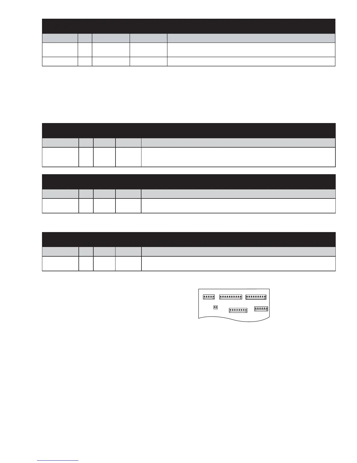
Some of the low voltage DC
connector labeling on this model
may differ from other models. The
function and diagnostics for these
connectors are identical for all
models.
Note: The J15 connector controls compressor speed through voltage AND frequency. When the main
board calls for compressor operation, J15 output between pins 1 and 2 should be approximately 5 VDC
with the harness connected and approximately 12 VDC with the harness disconnected. The voltage will
not change regardless of compressor speed. A change in frequency controls the compressor speed.
SNOITINIFEDNIPDRAOBLORTNOC
ROTCENNOC NIP TUPNI TUPTUO NOITCNUF
J15
J15
1
2
VDC
Common
12V variable frequency square wave to control compressor speed.
SNOITINIFEDNIPDRAOBLORTNOC
ROTCENNOC NIP TUPNI TUPTUO NOITCNUF
9J1 CAV
sitiucricsihtgnolwohstnuocremitA.CAV021-tiucrictsorfedehtotegatlov1LdehctiwS
roevitpadasie
lcyctsorfedtxenehtfienimretedotnoitamrofnisihtsesudnadezigrene
.evitpadano
n
SNOITINIFEDNIPDRAOBLORTNOC
ROTCENNOC NIP TUPNI TUPTUO NOITCNUF
11J1CAV .slanimret1LdehctiwsroflaitnetoptupniCAV021-stiucricdraoblortnocotegatlov1Ltnatsno
C
SNOITINIFEDNIPDRAOBLORTNOC
ROTCENNOC NIP TUPNI TUPTUO NOITCNUF
21J1 CAV. retaehnapniardehtotegatlov1
L

 Loading...