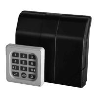
The Cody Universal 2 is a sophisticated access control device comprising a decoder and a control element, designed for direct control of tubular motors or similar equipment. Its robust design and versatile programming options make it suitable for various applications requiring secure access.
Function Description:
The core function of the Cody Universal 2 is to provide secure access control through programmable pass codes and transponder keys. The device connects via a simple two-wire cable, eliminating the need for special plugs. Programming is primarily done via the keypad using an 8-digit master code.
Upon entering a valid pass code, users can operate a motor in "dead man" mode using the UP ▲ and DOWN ▼ arrow keys. The two potential-free relay outputs are electrically interlocked, preventing simultaneous activation and ensuring safe operation. The relays remain active only as long as the arrow keys are pressed. After a preset period (factory default 60 seconds), the device automatically locks. This "Tiptomatic" function can be interrupted by pressing the STOP button.
The device supports up to 50 different 4 or 5-digit pass codes, allowing individual access for multiple users. A unique feature allows users to press any number of keys before entering their actual code, enhancing security against observation.
An optional "Cody Universal Service Tool" (Ref. 500.STU0.00) is available, offering convenient programming via an LCD display. This tool provides detailed information on programming steps, memory slot usage, and relay settings, and allows direct deletion of transponders by memory slot.
The "Lock-out function" provides an additional layer of security. If activated, the device blocks any input for a programmable period after an incorrect pass code entry, signaled by three beeps. A long sound signal indicates the end of the lock-out period.
Technical Specifications:
- Supply Voltage: 230-240 V AC
- Output: 250V AC 5A
- Connections: 1.5 mm² max.
- Ambient Temperature: -20 °C to +60 °C
- Memory Slots: Up to 50 different pass codes (00-49)
- Transponder Keys: Distributed among three blocks, each capable of storing 255 keys of a single color. The blocks correspond to the first three DIP switches.
- Tiptomatic Time: Factory default 60 seconds (programmable 001-255). This time is the same for all relays.
- Lock-out Time: Factory default 20 seconds (programmable 001-255). Can be set to "dynamic" (extended by 10 seconds with each wrong entry, max. 255 seconds) or "static" (fixed duration, 000 for turned off).
- Compliance: EC Electromagnetic Compatibility Directives (EN 61000-6-1 08/2002, EN 61000-6-3 08/2002) and Low Voltage Directive 2006/42/EC.
Usage Features:
- Mastercode: An 8-digit numeral code (factory preset: 12345678) is required for all programming procedures. It is crucial to change this to a personal master code for security.
- Pass Code: 4 or 5-digit numeral codes (factory preset for slot 00: 1234) for operating the door drive unit. Up to 50 unique pass codes can be stored.
- General Reset: Restores all factory settings: all memories erased (except 00), master code 1-8, pass code 00 (1-4), Tiptomatic time 60 sec., and lock-out time 20 sec. This is performed by setting DIP switch 4 to ON, pressing the reset button on the PCB for >5 seconds, then setting DIP switch 4 back to OFF.
- Programming a New Mastercode (Program 1): Enter the current 8-digit master code, press the button (sound signal 2x long), press '1' (sound signal 1x long), then enter the new 8-digit master code, and press the button (sound signal 1x long).
- Creating a New Pass Code (Program 2): Enter the 8-digit master code, press the button (sound signal 2x long), press '2', enter the 2-digit memory slot (e.g., 07 or 28), enter the 4 or 5-digit pass code, and press the button (sound signal 1x long).
- Deleting a Pass Code (Program 3): Enter the 8-digit master code, press the button (sound signal 2x long), press '2', enter the 2-digit memory slot, press the button (sound signal 1x long).
- Changing Tiptomatic Time (Program 4): Enter the 8-digit master code, press the button (sound signal 2x long), press '3', press '2', enter the 3-digit time (001-255), and press the button (sound signal 1x long).
- Changing Lock-out Time (Program 5): Enter the 8-digit master code, press the button (sound signal 2x long), press '3', press '3', enter the 3-digit time (001-255), and select 'dynamic' or 'static' by pressing the corresponding button (sound signal 1x long).
- Entering a Pass Code (Program 6): Enter the 4 or 5-digit pass code, press the button (sound signal 1x long). A correct code activates the corresponding relay. Incorrect codes trigger a 3-beep sound signal and initiate the lock-out period.
- Transponder Key Teach-in (Program 1): Set the DIP of the desired relay or block (1/2/3) to ON, present the desired key to the reader (LED flashes 1x long), then set all DIPs to OFF.
- Deleting Specific Transponder Keys (Program 2): Set the DIP of the taught-in key to ON, present the desired key to the reader (LED flashes 2x long), then set all DIPs to OFF.
- Deleting All Transponder Keys of a Block: Set the DIP of the specific block or relay (1/2/3) to ON, press the reset button on the logic board for >5 seconds, then set all DIPs to OFF.
Maintenance Features:
- Assembly and Connection: Must only be executed by appropriately trained personnel, adhering to national and local regulations.
- Interior Mounting:
- Open the enclosure by inserting a screwdriver into the gap and pushing up.
- Remove the control PCB.
- Locate and install the supplied screwed glands (sealing nipple on the left side) in the enclosure, then replace the PCB, ensuring it is firmly in position.
- Bore fastening holes and fix the enclosure bracket to the wall.
- Route wires for the keyboard through the left cable entry, relay contacts through the middle cable entry, and supply voltage through the right cable entry. Ensure tight seating of sealing nipples and cable glands to maintain water protection.
- Connect wires to the corresponding terminals according to the connection diagram.
- Warranty: The manufacturer (geba GmbH) is released from guarantee and product liability if the unit is modified without prior permission, or if the installation is improper or not in accordance with the instruction manual. The installer is responsible for respecting EMC regulations.
- Reader Mounting: The transponder reader should not be mounted directly on metal. A spacer case (No. 508.000G.00) should be used in such instances.
- Key Color Restriction: It is not possible to teach-in keys of different colors in one and the same block.