3
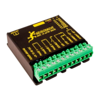
G201 STEP MOTOR DRIVE
REV 16: August 6, 2009
Connect the DIRECTION line to this terminal.
TERMINAL 9 Step
Connect the STEP line to this terminal.
TERMINAL 10 Common
Connect this terminal to the controller +5VDC power supply
These inputs are optically isolated from the rest of the drive. Terminal 10 is the common anode connection for the opto-isolators
and must be connected to the +5 VDC supply of your indexer or pulse generator.
These inputs are meant to be driven by standard TTL logic or other driver capable of sinking 16mA of current. The minimum logic
“0” time is .5uS while the minimum logic “1” time is 4uS. Microstepping occurs on the falling edge of the step input.
CURRENT SET RESISTOR
TERMINAL 11 Current Set
Connect the current set resistor to this terminal.
TERMINAL 12 Current Set
Connect the other end of the current set resistor to this terminal.
This input programs the G201A’s current output to the motor windings. The G201 will accommodate motor winding currents from
1 to 7A and 0.3 to 2A. Use the following equation to calculate the value, (in kilo-ohms) of the current set resistor:
R (in kilo-ohms) = 47 * I / (7 – I) or for the low current range, R = 47 * I / (2 – I)
Here are the current set resistor values for motor current in .5A increments. Round the appropriate answer to the nearest 5%
resistor value.
a. 1A – 7.8K
b. 1.5A – 12.8K
c. 2A – 18.8K
d. 2.5A – 26.1K
e. 3A – 35.25K
f. 3.5A – 47K
g. 4A – 62.67K
h. 4.5A – 84.6K
i. 5A – 117.5K
j. 5.5A – 172.33K
k. 6A – 282K
l. 6.5A – 611K
m. 7A – OPEN
HEATSINKING
The G201 needs heatsinking for current settings greater than 3 amps. The case temperature (measured on the bottom plate)
should not exceed 70 degrees C, and for best life should be kept to 50 degrees or less. Use heatsink compound between the
G201 and the heatsink.
CAUTION!
Current settings above 3 Amps without a heatsink will result in damage to the G201.
The drive must be heatsinked to a piece of aluminum, preferably with fins and a fan to increase heat dissipation and surface area.
Do not screw the drives directly to the door of your control cabinet, as this will typically not provide adequate heatsinking
properties.
OPTION JUMER BLOCK
The G201 has four settable options. These options are enabled and disabled via the jumper block shunt settings. See the
diagram below for how to set the shunts. The four options are described below.
(1) AUTO CURRENT REDUCTION: The G201 reduces motor phase current to 33% of the set value when the motor is stopped.
If enabled, this reduction occurs 1 second after the last step pulse is sent to the drive. Auto current reduction can be enabled or
disabled.
 Loading...