The Geckodrive G201X / G210X is a step motor drive designed for controlling stepper motors. It is 100% backwards compatible with the G201 and G210 models, offering several new features and performance enhancements.
Function Description:
The G201X / G210X is a microstep drive that controls the current to stepper motor windings, enabling precise motor movement. It accepts step and direction signals from a controller or pulse generator and translates them into microsteps. The drive features a recirculate mode during standby to reduce motor heating when stopped and includes a power-on reset function. For the G210X model, an onboard step pulse multiplier (G901X) allows for adjustable microstep resolution, including full step, half step, 5 microstep, and 10 microstep modes. Even in full stepping mode, the drive internally operates at its normal microstepping rate and morphs to full step at higher speeds to maximize torque.
Important Technical Specifications:
- Supply Voltage: 18 VDC (minimum) to 80 VDC (maximum).
- Motor Current: 0 A (minimum) to 7 A (maximum).
- Power Dissipation: 1 W (minimum) to 13 W (maximum).
- Temperature Range: 0 °C (minimum) to 70 °C (maximum).
- Humidity: 0% (minimum) to 95% (maximum).
- Motor Inductance: 1 mH (minimum) to 50 mH (maximum). Recommended motor winding inductance should be 500uH or greater, but generally no more than 7mH.
- Input Frequency: 0 kHz (minimum) to 200 kHz (maximum).
- Step Pulse "0" Time (COMMON 3.3V-5V): 0.5 us.
- Step Pulse "1" Time (COMMON 3.3V-5V): 3 us.
- Step Pulse "0" Time (COMMON GND): 3 us.
- Step Pulse "1" Time (COMMON GND): 0.5 us.
- Direction Setup: 0 us (minimum).
- Signal Voltage: 3.3 VDC (minimum) to 5 VDC (maximum).
- Weight: 3.6 oz.
- STEP and DIRECTION Compatibility: +3.3VDC and +5VDC compatible at 2.5mA.
- Power Supply Current: Maximum required is 67% of the motor's rated phase current. Ripple voltage should be 10% or less.
- Power-on Reset Time: 2 seconds before the motor is energized.
- Logic Input Current: Capable of sourcing or sinking 2.5mA.
- Microstepping: Occurs on the falling edge of the step input when COMMON is a positive voltage, and on the rising edge when COMMON is connected to GND or 3.3V-5V.
Usage Features:
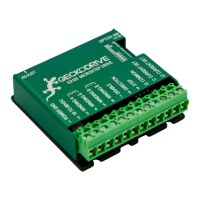
- Terminal Wiring: The drive uses a 2-piece modular main connector. Terminals 1-6 handle power supply and motor leads, while terminals 7-12 manage the control interface. These connectors can be removed for mounting.
- Terminal 1 (Power Ground): Connects to the negative (black) lead of the power supply.
- Terminal 2 (Power +): Connects to the positive (red) lead of the power supply (+18VDC to +80VDC).
- Terminals 3 & 4 (Motor Phase A & /A): Connects one motor winding.
- Terminals 5 & 6 (Motor Phase B & /B): Connects the other motor winding.
- Terminal 7 (Disable): Forces winding currents to zero when shorted to Terminal 12. The drive continues to totalize step and direction inputs. Motor returns to original position if no steps sent and motor moved less than 2 full steps.
- Terminal 8 (Direction): Connects the DIRECTION signal.
- Terminal 9 (Step): Connects the STEP signal.
- Terminal 10 (Common): Connects the controller's +3.3VDC, +5VDC, or GND. These inputs are optically isolated.
- Terminals 11 & 12 (Current Set - OPTIONAL): Connects an external current set resistor.
- Motor Connection: Supports 4-wire, 6-wire, and 8-wire motors. 6-wire motors can be connected in half winding or full winding (equivalent to 8-wire in parallel or series). Reversing motor direction can be done by swapping connections to terminals 3 and 4.
- Current Setting: Motor current can be set in 0.2A increments using onboard DIP switches (SW1-SW5) or with an external current set resistor connected to Terminals 11 and 12. If using an external resistor, SW1-SW5 must be "ON". The resistor value in kilo-ohms is calculated as R = 47 * I / (7-I).
- Automatic Current Standby (SW9): Reduces motor phase current to 70% of the set value when the motor is stopped (1 second after the last step pulse). This reduces motor heating by up to half. Full current is restored immediately upon step pulse resumption. Enabled when SW9 is "ON", disabled when "OFF".
- NEMA-34 and NEMA-42 Motor Option (SW10): Adjusts the midband compensation circuit for optimum performance with NEMA-34 and NEMA-42 motors. Enabled when SW10 is "OFF", disabled when "ON" (for NEMA-17 and NEMA-23 motors).
- Low Speed Smoothness Adjust Trimpot: Allows adjustment for the smoothest possible low-speed operation. Set motor speed to about 1/2 revolution per second and turn the trimpot until a null in motor vibration is noted.
- Microstep Resolution (G210X/G901X): Set using a 2mm jumper block and two jumpers. Options include Full Step, Half Step, 5 µSTEP, and 10 µSTEP. Power must be off before adjusting jumpers.
Maintenance Features:
- Heatsinking: Required for current settings greater than 3 Amps. The case temperature (bottom plate) should not exceed 70°C (preferably 50°C or less) for best life. Heatsink compound should be used between the drive and the heatsink. Damage will occur without adequate heatsinking above 3 Amps.
- Restoring Factory Defaults: Set the trimpot to the 11 o'clock position and set SW1-SW10 to "ON".
- Technical Support: Geckodrive offers free technical support and a three-year warranty against workmanship defects.
- Cautions:
- Power supply voltage exceeding 80 VDC will damage the G201X.
- Never put a switch on the DC side of the power supply.
- Power supply voltage should be no less than 4 times and no more than 25 times the motor's rated voltage.
- Do not short motor leads to each other or to ground.
- Turn off power supply when connecting or disconnecting the motor.