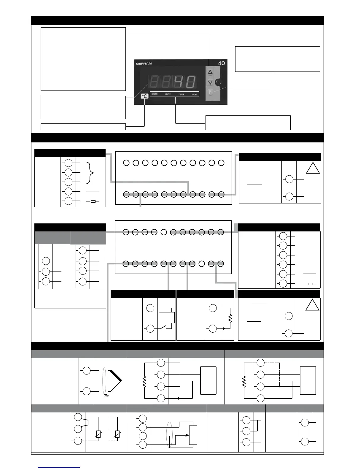
3 • DESCRIPTION OF FRONT PANEL
Use wires of
adequate thickness
(min. 1mm
2
)
PT100, JPT100,
PTC, NTC
• Pt100 / PTC / NTC
3
1
2
3-wire
PT100
2-wire PT100
PTC / NTC /
Generic user
configurable outputs
Out1
- relay 5A/250Vac
- Triac
20...240Vac ±10%
1A max
Out2
- relay 5A/250Vac
- logic 24V/20mA,
Out3
- relay 5A/250Vac
Available thermocouples:
J, K, R, S, T, B, E, N,
L, U, G, D, C
- Respect polarities
- For extensions,
use compensated
cable appropriate for
thermocouple.
dc current
linear input
20mA, Ri = 50Ω
dc voltage
linear input
60mV, 1V
Ri > 1MΩ
5V, 10V
Ri > 10kΩ
“Raise” and “Lower” keys:
These keys are used for any operation that
requires a numerical parameter to be raised or
lowered. •• The speed of change is proportional
to the time the key is pressed. •• The operation
is not cyclic: once the maximum (minimum) limit
is reached, there will be no further increase
(decrease) of the value, even if the key remains
pressed.
The keys can be configured to perform
reset, hold, display of the peak value, etc. as
determined by the ‘t.U.’ and ‘t.d.’ parameters on
the ‘In’ menu.
Function key:
Gives access to different configuration stages ••
Confirms any parameter changes
Standard:
100 to 240VAC/DC
±10%
Optional: 11 to
27VAC/DC ±10%
50/60Hz, 8VA max.
• Linear (V)
• Outputs
2
1
+
-
• Linear (I)
4
1
2
-
+
12
14
13
15
Out3
-
+
Out2
• Power supply
11
10
~
~
+
-
• Inputs
• Thermocouples
2
1
4
2
3
1
+
-
+
+
S
-
Ri = 50Ω
to connect for 20mA input
4
2
3
1
+
-
+
+
-
Ri = 50Ω
4...20mA
• Linear input with 3-wire transmitter
• Linear input with 2-wire transmitter
PWR
Indication of output states:
OUT 1 (Alarm 1); OUT 2 (Alarm 2);
OUT 3 (Alarm 3); OUT 4 (Alarm 4)
114 5 1083 972 61
1219 18 131520 141621 1722
!
Label with engineering units
16
17
Out1
4 • CONNECTIONS
Digital input
24V, 5mA
or no-voltage
contact
6
5
+
-
• Digital input
Analog retrans.
output
0...20mA,
Rmax. 500Ω
0...10V
Rmin. 10KΩ
Out4
- relay 5A
250Vac
8
7
•
Retransmiss. output/Out4
+
-
R
• Linear input 1V for potentiometer
4
2
3
1
R >100Ω
External
supply
PV display: Indication of process variable • •
Indication of ‘HI’ or ‘Lo’ out of range •• Indication
of open circuit (br) or short circuit (Er)
•• Display of configuration and calibration
messages
T
T
~
~
Load
VT VT
Modbus 4 wires
/ Cencal
Modbus 2 wires
(Standard)
• Serial line
RS485 isolated serial line
For configuration Modbus 4 wires/Cencal
sees sheet technical
20
22
21
19
21
20
+
22
-
+
-
GND
B
(data -)
A
(data +)
Rx
Tx
24V or 15V 24V or 15V
Generic user
configurable
outputs
Out1
- relay
5A/250Vac
Out2
- relay
5A/250Vac
Standard:
100 to 240VAC/DC
±10%
Optional: 11 to
27VAC/DC ±10%
50/60Hz, 8VA max.
• Outputs
8
9
7
no
• Power supply
11
10
~
~
PWR
114 5 1083 972 61
1219 18 131520 141621 1722
!
6
5
Out2
~
~
Load
c
nc
Out1
Inputs
Mod. 40T 96 _ _ 2R (base)
Mod. 40T 96 _ _ RR/RD/T0 (expandible)
2
81641I_MHW_40T96_07-2011_ENG
-
+
+ 1,2V
 Loading...