5 • HARDWARE CONFIGURATION
Accessing the boards
To remove the electronic parts from the case, open the extraction clips.
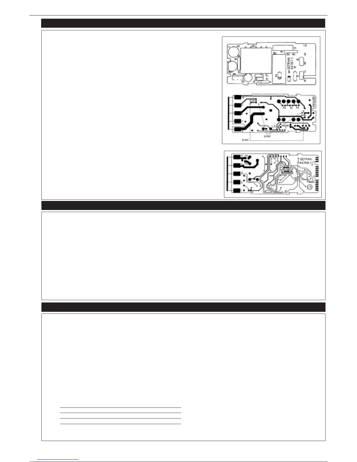
Power board Fig. 1
To select the supply voltage 110/220Vac (24/240Vac):
-110V (24/120V) - close the two jumpers marked P2 and open the jumper marked S2.
220V (48/240V) - close the jumper marked S2 and open the two jumpers marked P2.
To select AC/DC voltage: double jumper S1 (See Fig. 1 power board, solder side).
AC voltage: since this is the standard version, the two jumpers S1-AC are already on the
printed circuit.
DC voltage: cut the two jumpers S1-AC and solder two jumpers in position S1-DC.
CPU-inputs boards
Hardware protection of configuration.
- Configuration disabled: close jumper S2 and remove jumper S3.
- Configuration enabled: close jumper S3 and remove jumper S2.
The standard version is supplied with configuration enabled.
Selection of relay R2 contact:
NO (normally open) / NC (normally closed).
NO: close NO jumper and remove NC jumper.
NC: close NC jumper and remove NO jumper.
The standard version is supplied with contact configured NO.
6 • PROGRAMMING
POWER BOARD
CPU BOARD
Programming the TIMER:
In normal operation, display A shows the real value of the active time (if Time 2 is active, the decimal point flashes on the right display).
The setpoints for Time 1 (and Time 2) are set by pressing the Raise/Lower buttons.
If the Timer is active, push the raise or lower button to recall the Time 1 setting, then use these buttons for a new setting. Select Time 2 with the F key.
The setting of Time 1 is immediate while Time 2 must be selected using the F key. When the setting has been made, press the F key to return to normal
operation. If the F key + raise button are pressed simultaneously for about 3 sec, the instrument will display the software release.
Programming the COUNTER:
In normal operation, display A shows the real value of the active count (if count 2 is active, the decimal point flashes on the right display).
The setpoints for Count 1 Time 2/Count 2 are set by pressing the Raise/Lower buttons.
If the Counter is active, push the raise or lower button to recall the Count 1 setting, then use these buttons for a new setting. Select Time 2 / Count 2 with
the F key. When the setting has been made, press the F key to return to normal operation.
Programming can be disabled by setting the software password to 1 (see Configuration phase, “Pro” function).
Note: the maximum counting frequency is 100Hz.
7 • SOFTWARE CONFIGURATION
Introduction
Configuration (CFG) is performed in a single procedure and consists of 9 settable parameters.
To access Configuration (if the hardware protection has been removed), press the F key until the CFG message appears on display A.
Then press the F key briefly to scroll the various functions (parameters) to be set so that the instrument can be configured as required. The display alter-
nately shows the symbol and the value of the parameter.
The raise and lower buttons stop this alternation so that the value to be seen and/or changed remains on the display. Alternation resumes if no button is
pushed for about 5 sec. Press the F key for about 5 seconds to quit the configuration procedure. The display returns to the “real” time/count.
Configuration parameters are visible only when applicable, depending on the type of operation selected.
Configuration (CFG) procedure
Configuration (CFG)
(accessible only with jumper S3 closed)
Pro/software protection level in range 0-2 according to table:
LEVEL DISPLAY ONLY DISPLAY AND
CHANGE
0 SETPOINTS
1 SET POINTS
2 MAX. PROTECTION MAX. PROTECTION
NOTE: At level 2, the instrument displays the time or current counter only (standard protection level: 0).
3
80310B_MHW_550_0609_ENG
 Loading...