_________________________________________________________________________
ADV200
Instruction manual
EXP-DE-I1R1F2-ADV
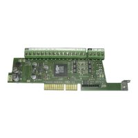
Digital Incremental (DE)
Encoder expansion card S5L30
• 1 TTL/HTL Encoder Input
• 1 TTL/HTL Encoder Output Repetition
• 2 Channel freeze
Questa scheda può essere utilizzata solo con drive ADV200 versione firmware 3.0 e successive
This card can be used only with drive ADV200 firmware version 3.0 and later
Isolamento funzionale - Functional insulation
FELV (Functional Extra Low Voltage) EN 61800-5-1
Introduzione / Introduction
Scheda di espansione per un ingresso / uscita encoder digitale optoisolato TTL/
HTL per i drive ADV200.
E' possibile montare fino a due schede encoder per Drive, per maggiori dettagli
vedere il capitolo 5.4 del manuale ADV200 Guida Rapida all'installazione.
Gli ingressi Freeze congelano la posizione encoder e sono utilizzati solo da MDPlc
The card adds 1 digital TTL / HTL optocoupled encoder input / 2 freeze inputs / 1 output to
the ADV200 drive.
It’s possible to mount up to 2 encoder cards for each drive; for more details see chapter 5.4
of ADV200 Quick Start Up Guide.
The Freeze inputs store the encoder position and can be used only by MDPlc.
Fissaggio / Mounting
Fare riferimento al capitolo Installazione schede opzionali del manuale
ADV200 Guida rapida all'installazione.
Refer to ADV200 Quick Start up manual, chapter Installation of optional cards.
ATTENZIONE: Utilizzare solo le viti in dotazione !
CAUTION: Use only the supplied screws !
Possono essere inserite fino a tre schede opzionali nei tre alloggiamenti
(Slot) che si trovano sotto la copertura superiore:
• Slot 1: dedicato alle schede IO (EXP-IO-...-ADV) (*)
• Slot 2: dedicato alle schede Encoder (EXP-...-ADV)
• Slot 3: dedicato alle schede Bus di campo (EXP-PDP-ADV, EXP-CAN-ADV,
ecc) (*)
Up to three optional cards can be inserted in the three slots under the top
cover:
• Slot 1: dedicated to IO cards (EXP-IO-...-ADV) - (*)
• Slot 2: dedicated to Encoder cards (EXP-...-ADV)
• Slot 3: dedicated to field Bus cards (EXP-PDP-ADV, EXP-CAN-ADV, etc.)(*)
(*) Nel caso sia necessario gestire 2 o 3 encoder, in questi Slot possono essere inserite anche le
schede per gli encoder digitali (EXP-DE-I1R1F2-ADV e EXP-DE-I2R1F2-ADV), vedere il capitolo
11.5.1 del manuale ADV200 Guida rapida per maggiori dettagli.
(*) If managing 2 or 3 encoders, these slots can also be used for the digital encoder cards (EXP-
DE-I1R1F2-ADV and EXP-DE-I2R1F2-ADV), see section 11.5.1 ADV200 Quick Start up manual,
for further details.
Importante! Se viene inserita una scheda opzionale in uno Slot errato, il drive segnalerà
un messaggio di errore.
Attention! If an optional card is inserted in an incorrect Slot, the drive will send an
error message.