Chapter 14 - Set-up & Assembly
Printed in U.S.A. 41 909793/BP0805
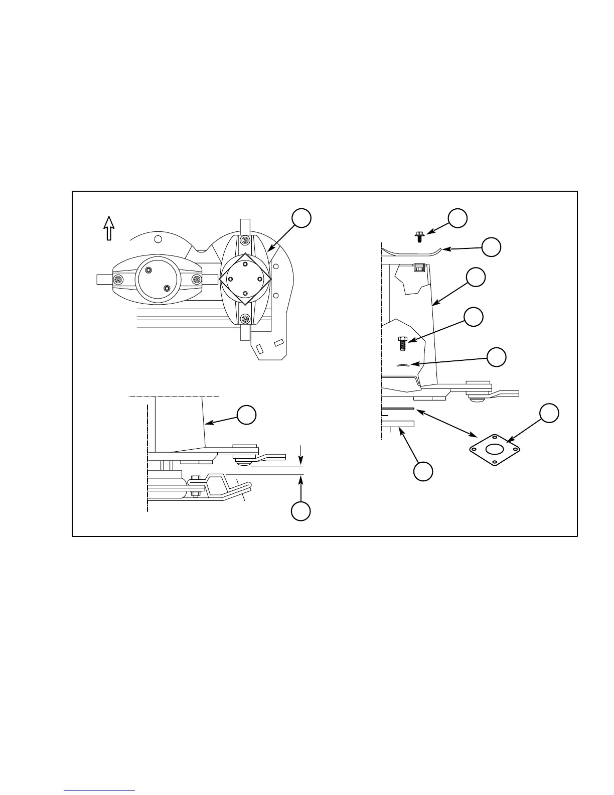
Outer Disc Installation
10. Refer to Fig. 41. Position the outer disc assembly
(Ref. 1) on the rightmost cutterbar hub so that the
knives are positioned at a right angle in relation to
the adjacent disc as shown at “A”. Then, install the
disc using four M12 x 20 mm cap screws (Ref. 2),
four conical washers (with conical center up - see
“B”, Ref. 3) and, if necessary, a shim plate (Ref.
4) — see NOTE, below. Tighten the cap screws to
90 ft.-lbs. (120 Nm) torque.
NOTE: Use a 1 mm thick shim plate (Ref. 4) be-
tween the disc and the hub ONLY if the clearance
(Ref. 6) between the knife mounting bolts and the
top of the cutterbar is less than 3/64 in. (1 mm).
11. Install the curved cover (with the turned-up cor-
ners facing up, Ref. 7) using four self-locking cap
screws (Ref. 8). Tighten the cap screws to 65 ft.-
lbs. (85 Nm) torque.
1 - Outer Disc Assembly
2 - M12 x 20mm Cap Screws (4 used)
3 - Conical Washer (4 used)
4 - 1 mm Thick Shim Plate
Fig. 41: Outer Disc Installation
3
2
1
4
7
8
6
5
1
1
“B”
“C”
“A”
5 - Cutterbar Rightmost Hub
6 - 3/64 in. (1 mm) Clearance Minimum
7 - Curved Cover
8 - Self-locking Cap Screws