Chapter 14 - Set-up & Assembly
909793/BP0805 42 Printed in U.S.A.
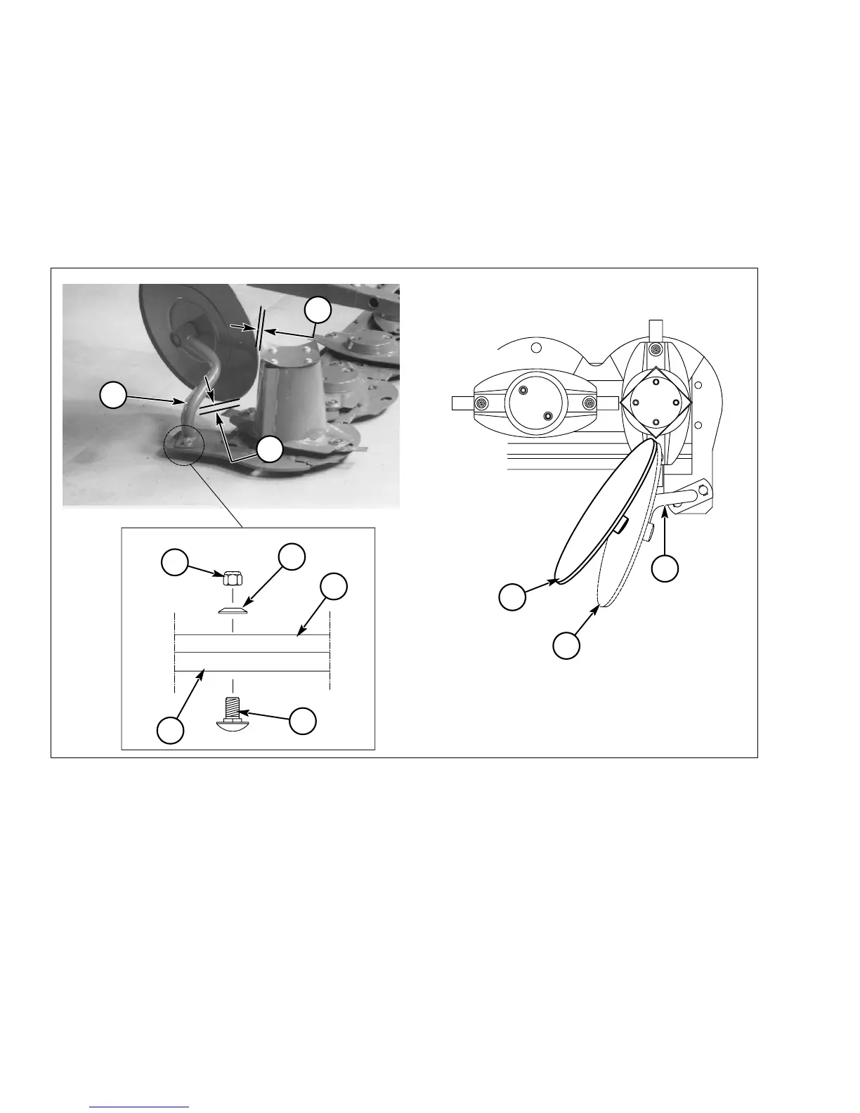
Outer Swath Wheel Installation
12. Refer to Fig. 42. Loosely install the swath wheel
assembly (Ref. 1) to the outer skid shoe (Ref. 5)
using two M12 x 35 mm carriage bolts (Ref. 2),
two conical washers (Ref. 3 - with conical center
towards the lock nut, as shown) and two M12 lock
nuts (Ref. 4). Make sure the swath wheel is at least
5/8 to 1 in. (15 to 25 mm) away from the corners
of the curved cover and the blades, as shown as
Ref. C.
13. The angular position of the swath wheel deter-
mines the flow of the cut crop towards the rear. For
most working conditions and crops, the swath
wheel should be set at the maximum angle (Ref.
A). In difficult working conditions (long, dense,
bent over crops) position it more towards the mini-
mum angle (Ref. B).
14. After setting the swath wheel to the desired posi-
tion, tighten the lock nuts (Ref. 4).
1 - Swath Wheel Assembly
2 - M12 x 35mm Carriage Bolt (2 used)
3 - 13mm Diameter Conical Washer (2 used)
4 - M12 Lock Nut
Fig. 42: Outer Swath Wheel Installation
5 - Outer Skid Shoe
A - Maximum Angle (Normal Position)
B - Minimum Angle (Difficult Crop Position)
C - 5/8 to 1 in. (15 to 25 mm)
3
2
1
4
A
5
1
1
B
C
C