Chapter 14 - Set-up & Assembly
Printed in U.S.A. 43 909793/BP0805
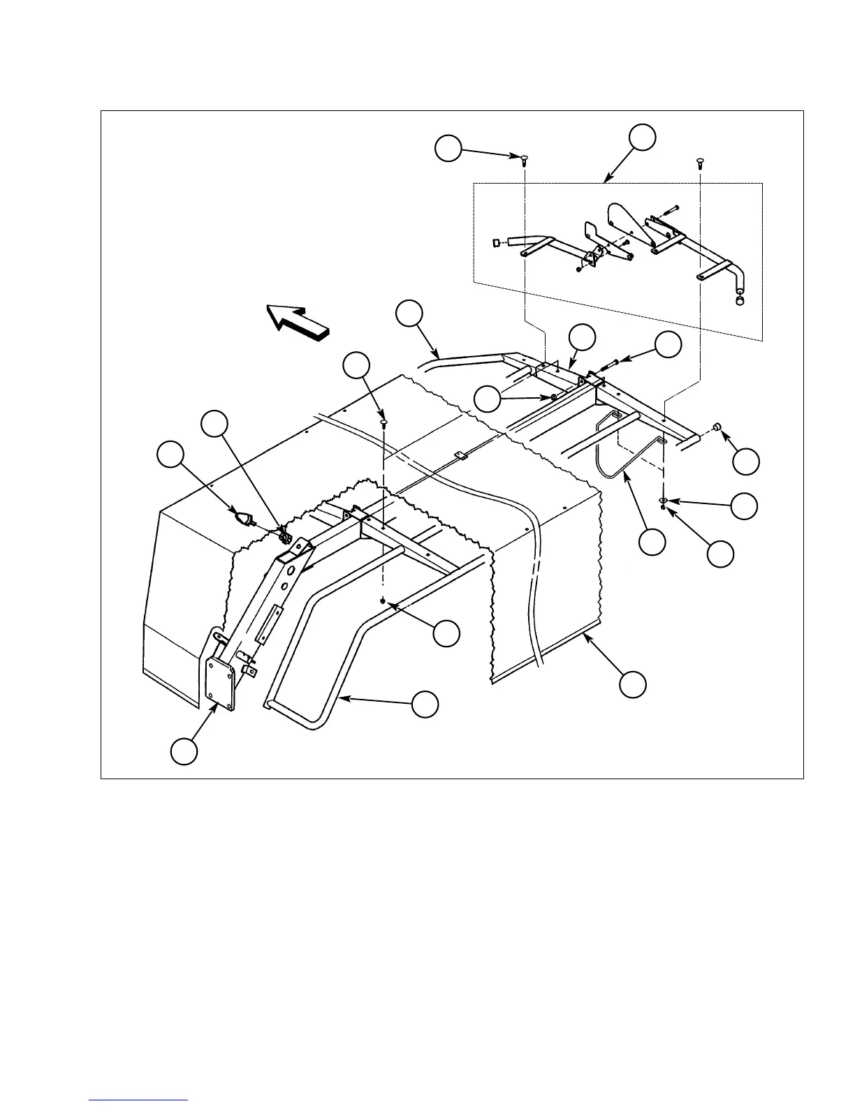
Protective Cover Installation
1 - Front Safety Bar
2 - Hinge (1 of 3)
3 - M10 x 25 mm CB (10 used)
4 - M10 LN (10 used)
5 - M12 x 75 mm CS (3 used)
6 - M12 LN (3 used)
7 - Protective Cover Frame
8 - Rear Safety Bar
Fig. 43: Protective Cover Installation
9 - Plug
10 - Protective Cover
11 - Stop Rod
12 - Locking Device (Preassembled at the Factory)
13 - M10 x 35 mm CB (3 used)
14 - 11 x 24 x 2 mm FW (3 used)
15 - Rubber Bumper
16 - M8 LN
3
2
1
4
7
8
9
10
11
12
13
14
15
16
6
5
4
A
A
A
Front
15. Refer to Fig. 43. If not already assembled, attach
the three hinges (Ref. 2) to the front safety bar
(Ref. 1) using five each carriage bolts (Ref. 3) and
lock nuts (Ref. 4).
16. Install the front safety bar (with hinges) to the pro-
tective cover frame (Ref. 7) using three each cap
screws (Ref. 5) and lock nuts (Ref. 6). DO NOT
overtighten the cap screws — the front safety bar
must be able to pivot.