Chapter 14 - Set-up & Assembly
909793/BP0805 44 Printed in U.S.A.
17. Install the rear safety bar (Ref. 8) with five car-
riage bolts (Ref. 3) and five lock nuts (Ref. 4).
18. Install the plug (Ref. 9) on the rear safety bar (Ref.
8).
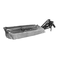
19. Position the protective cover (Ref. 10) over the
frame as shown. Buckle all off the straps around
the frame and front and rear safety bars. These
straps are attached to the insude of the protective
cover.
20. Punch three holes in the protective cover where
the locking device (Ref. 12) will be installed —
see reference (A). Then use three each carriage
bolts (Ref. 13), flat washers (Ref. 14) and lock
nuts (Ref. 4) to loosely attach the following com-
ponents on the outside arms of the safety bars:
• locking device (Ref. 12)
• protective cover (Ref. 10); and
• stop rod (Ref. 11).
NOTE: Be sure that the pivot axis of the locking
device (Ref. 12) is lined up with the pivot axis of the
front safety bar before tightening the lock nuts (Ref.
4).
NOTE: The protective cover locking device
(Ref. 12) is operated with an 18 mm box wrench
which is included with the mower. Refer to the Con-
trols and Safety Equipment chapter for proper use
of this tool.
CAUTION
ALWAYS operate the disc mower with the pro-
tective cover in place and the front safety bar
lowered. Never lean against or stand on the
cover. NEVER operate with the protective cov-
er in the raised position.
NOTE: The protective cover locking device
(Ref. 12) is operated with an 18mm box wrench
which is included with the mower. Refer to the Con-
trols and Safety Equipment chapter in this manual
for proper use of this device.
Transport Position Stop Bumper
Installation
21. Install the rubber bumper (Ref. 15) on the protec-
tive cover frame using a lock nut (Ref. 16).
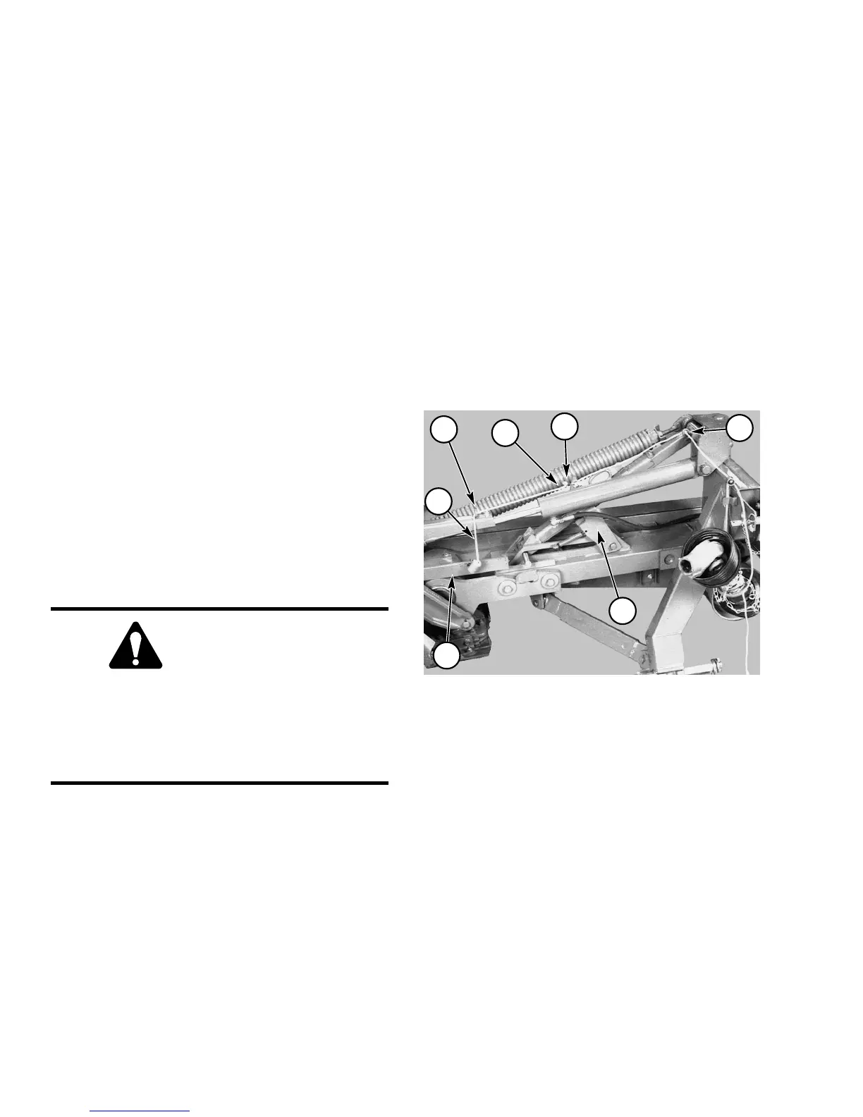
Transport Lock Control Cords
22. Refer to Fig. 44. Thread first cord from stop plate
through first eyelet. Attach the metallic hook to
the hole at the top of the transport latch and close
the hook’s eyelet with a pair of pliers. This cord is
factory installed to the stop plate.
23. Refer to Fig. 44. Thread the cord with handle at-
tached through the eyelet at the top of the hitch and
down to the hole at the top of the transport latch.
Secure with a knot. See Figure 44.
3
1 - Cord
2 - Cord Routing Eyelet
3 - Metal Hook
4 - Stop Plate
5 - Transport Latch
6 - Knot in hole at top of Transport Latch
Fi
. 44
2
1
2
4
5
6
PTO Drive
Attach the PTO driveline following the instructions
contained in the Preparing for Field Operation chapter.