913218/CP0307 36 PRINTED IN U.S.A.
Load Capacity and Reach
This machine has flip-charts in the operator’s station
that provide, at a glance, the load capacity limits at var-
ious positions of attachment tool extension and eleva-
tion. A set of the load zone charts is reproduced at the
end of this manual for reference.
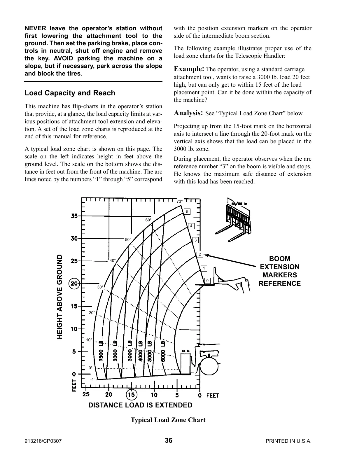
A typical load zone chart is shown on this page. The
scale on the left indicates height in feet above the
ground level. The scale on the bottom shows the dis-
tance in feet out from the front of the machine. The arc
lines noted by the numbers “1” through “5” correspond
with the position extension markers on the operator
side of the intermediate boom section.
The following example illustrates proper use of the
load zone charts for the Telescopic Handler:
Example: The operator, using a standard carriage
attachment tool, wants to raise a 3000 lb. load 20 feet
high, but can only get to within 15 feet of the load
placement point. Can it be done within the capacity of
the machine?
Analysis: See “Typical Load Zone Chart” below.
Projecting up from the 15-foot mark on the horizontal
axis to intersect a line through the 20-foot mark on the
vertical axis shows that the load can be placed in the
3000 lb. zone.
During placement, the operator observes when the arc
reference number “3” on the boom is visible and stops.
He knows the maximum safe distance of extension
with this load has been reached.
Typical Load Zone Chart
HEIGHT ABOVE GROUND
BOOM
EXTENSION
MARKERS
REFERENCE
DISTANCE LOAD IS EXTENDED
NEVER leave the operator’s station without
first lowering the attachment tool to the
ground. Then set the parking brake, place con-
trols in neutral, shut off engine and remove
the key. AVOID parking the machine on a
slope, but if necessary, park across the slope
and block the tires.
0
1
2
3
4
5
73°
60°
50°
40°
30°
20°
0°
10°
-4°
 Loading...