Do you have a question about the Gehl RS5-19 and is the answer not in the manual?
Symbol indicating potential safety hazards and the need for operator alertness.
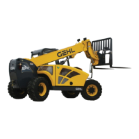
Details maximum lift capacity, height, and load at height.
Provides physical measurements like length, width, height, and wheelbase.
Lists engine type, displacement, power, torque, and features.
Checklist of inspections before delivering the machine to the customer.
Checklist of information to provide to the customer at delivery.
Steps to follow before performing maintenance or adjustments on the unit.
Essential checks and actions to perform before starting machine operation.
Guidelines for safe operation, including stability and movement.
Specific precautions for handling suspended loads safely.
Safety advice for performing maintenance and servicing.
Information on protective structures and audible/visual alerts.
Explains the purpose of guards and shields and safety decals.
Details the key switch, start button, and horn button functions.
Describes the location and components of the instrument panel.
Explains the multi-function display screen and its various functions.
Describes the function of various warning and status indicator lamps.
Explains the function of various switches for operation and equipment.
Details how to operate the cab's heating and air conditioning system.
Explains the function of the lever for forward, neutral, and reverse travel.
Describes controls for boom and attachment positioning.
Explains how to extend, retract, raise, and lower the telescopic boom.
Describes indicators like Frame Angle and Boom Angle.
Procedures for a thorough walk-around inspection before starting work.
Recommended procedure for safely starting the machine's engine.
Recommended procedure for safely shutting down the machine.
Explains the system that reduces emissions and its operation.
Instructions for attaching and detaching various work tools.
Guidelines for operating on inclines and slopes to maintain stability.
Lists types and specifications of lubricants for various machine components.
Specific hydraulic oil recommendations for harsh operating environments.
Instructions for greasing fittings to prevent contamination and wear.
Identifies locations of grease fittings for routine lubrication.
Critical safety warnings and requirements before performing service.
Identifies services that should only be performed by an authorized dealer.
Information on servicing the engine and hydrostatic transmission.
Details on servicing hydraulic system parts like pumps and cylinders.
Notes access to components located under covers for operator servicing.
Steps for checking and maintaining the engine oil level.
How to check the engine coolant level for proper operation.
Importance of proper tire pressure for stability and tire life.
Step-by-step guide for replacing engine oil and filter.
Guide for draining, flushing, and refilling the hydraulic reservoir.
Procedures for preparing and storing the machine for extended periods.
Instructions for properly applying new decals to the machine surface.
Visual guide showing the locations of various decals on the machine.
Schedule outlining required maintenance tasks at different intervals.
Template for recording completed maintenance procedures and dates.
| Fuel Type | Diesel |
|---|---|
| Tire Type | Pneumatic |
| Maximum Lift Height | 19 ft |
| Engine | Deutz TD 2.9L Tier 4 Final |
| Steering | 4-Wheel |
| Lift Height | 19 ft |