50960066/AP0813 18 PRINTED IN U.S.A.
Load Zone Charts: A
set of flip charts show
lift height and reach lim-
its relative to the load
weight being handled
with various attachment
tools.
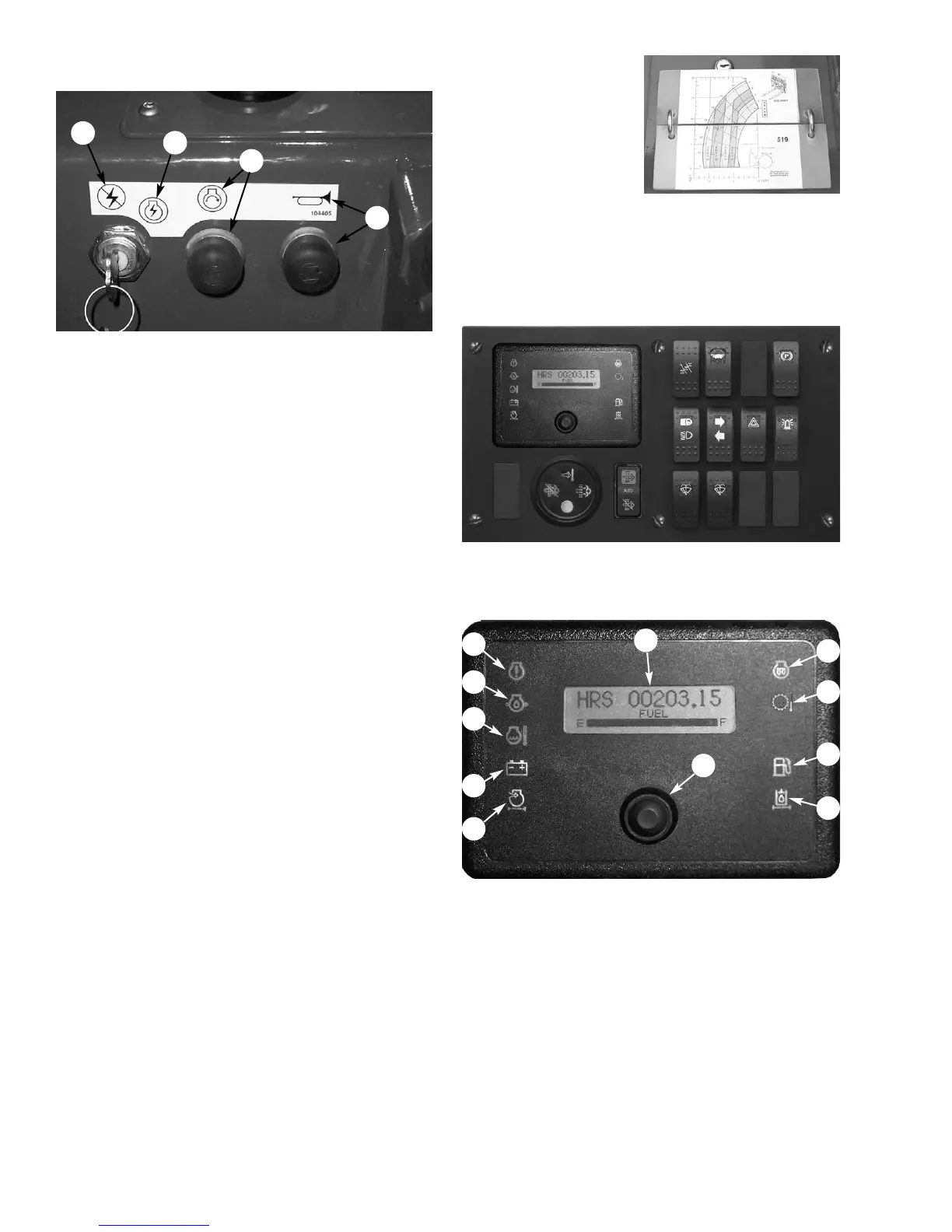
INSTRUMENT AND SWITCH PANEL
Located to the right of the steering wheel, this panel
contains the instrument gauges, indicator lamps and
function switches.
Instrumentation
A - Multi-Function Display Screen: This screen dis-
plays the following functions:
• fuel level at all times,
• engine coolant temperature,
• engine speed,
• voltmeter
• hourmeter
• 250 hour maintenance reminder
• error fault codes
• DPF regeneration status and level
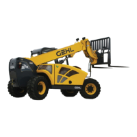
DASH PANEL AREA
A - Key switch OFF: When the key is vertical in the
keyswitch, power is disconnected from the battery to
the control and instrument panel electrical circuits.
Also, this is the only position in which the key can be
inserted or removed.
B - Key switch ON: When the key is turned one posi-
tion clockwise from the vertical (OFF) position, power
from the battery is supplied to all controls and multi-
function display panel electrical circuits. Indicators on
the multi-function display should light up momentari-
ly.
When the key is in this position, the engine pre-heat
indicator will stay on until the engine is pre-heated. In
colder temperatures the pre-heat indicator will stay lit
for 3-30 seconds. When the pre-heat indicator light
goes out the engine can be started.
C - Start Button: With keyswitch in ON position,
press the button to activate the starter. Release it as
soon as the engine starts.
NOTE: If the engine requires repeated attempts
to start, the key MUST be returned to the OFF
position between starting attempts to prevent bat-
tery run down.
IMPORTANT: Do not use additional starting aids
such as ether injection when using the electrical
engine preheat.
D - Horn Button: Press the horn button to activate
warning sound.
Instrument and Switch Panel
Key Switch, Start and Horn Buttons
A
D
C
B
A
E
D
C
F
G
J
I
H
K
B
 Loading...