EasyManua.ls Logo

Gehl RS8-44 User Manual

Gehl RS8-44
96 pages
To Next Page IconTo Next Page
Page #1 background imageLoading...
Page #1 background image
RS6-42
RS8-42
RS8-44
Telescopic Handlers
Operator’s Manual
Form No.
913218
Revision C
© 2007 Gehl Company • All Rights Reserved. • Printed in USA
Courtesy of CraneMarket.com
Question and Answer IconNeed help?

Do you have a question about the Gehl RS8-44 and is the answer not in the manual?

Gehl RS8-44 Specifications

General IconGeneral
Engine Power74 hp
Wheelbase10 ft 6 in
Overall Width8 ft 2 in
Fuel TypeDiesel
Lift Capacity8000 lbs

Summary

Chapter 1 INTRODUCTION

Safety Alert Symbol

Symbol indicating potential safety hazards and stressing the need for operator alertness.

Chapter 2 SPECIFICATIONS

Lifting Performance

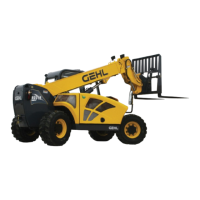
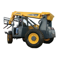
Details on machine weight, maximum lift capacity, and height.

Transmission

Specifications for transmission type, torque converter, and travel speeds.

Engine

Engine type, displacement, aspiration, and oil capacity.

Hydraulic System

Specifications for hydraulic system type, pump, pressure, and flow rates.

Chapter 3 CHECKLISTS

Pre-Delivery Inspection Checklist

Items to check before delivering the telescopic handler to the customer.

Delivery Information Checklist

Information to pass to the customer at the time of unit delivery.

Chapter 4 SAFETY

Safety Alert Symbol Meaning

Explanation of the safety alert symbol and its importance for operator awareness.

Mandatory Safety Shutdown Procedure

Steps required before cleaning, adjusting, lubricating, or servicing the unit.

SAFETY

Operation Safety Reminders

Key safety precautions to follow while operating the machine.

Servicing Safety Reminders

Important safety tips to follow when servicing the equipment.

Before Operation Safety Reminders

Checks and precautions to take before starting machine operation.

Safety Guards and Warning Devices

Personnel Work Platform (PWP) Safety System

Information on the optional PWP system and mandatory safety rules.

Mandatory Work Platform Safety Rules

Essential rules to follow when elevating personnel using the PWP system.

Work Platform Design Requirements

DASH PANEL AREA

Chapter 5 INDICATORS AND CONTROLS

Two Joystick Configuration

Single Tri-Function Joystick Configuration

Description of the tri-function joystick and its buttons/trigger.

ATTACHMENT TOOLS

Chapter 6 OPERATION AND ADJUSTMENTS

ENGINE BREAK-IN

Procedure and guidelines for breaking in a new engine for the first 100 hours.

PRESTART INSPECTION

Operator's responsibility for daily machine inspection before operation.

STARTING THE ENGINE

Recommended procedure for safely starting the machine's engine.

COLD STARTING PROCEDURES

STOPPING

Recommended sequence for safely stopping the machine.

ENGINE SHUTDOWN PROTECTION

Engine protection features for oil pressure and coolant temperature.

Engine Coolant Temperature

CHANGING ATTACHMENT TOOLS

Procedure for attaching and detaching Gehl attachment tools.

Quick-attach System Attaching Detail

GENERAL MACHINE OPERATION

Steps to perform before starting the machine for the first time each day.

Grade and Slope Precautions

Load Capacity and Reach

Information on load capacity limits based on extension and elevation using load zone charts.

Load Elevation and Placement

LIFTING ATTACHMENT TOOL APPLICATIONS

Procedures for picking up and carrying loads with attachment tools.

Installation of a Personnel Work Platform (PWP)

Steps for installing the optional Personnel Work Platform system.

PWP System

Elevating Personnel

Guidelines for using the PWP system to elevate personnel safely.

Suspended Loads

STORAGE

Chapter 7 LUBRICATION

Chapter 8 SERVICE AND STORAGE

POWER TRAIN COMPONENTS

Information on servicing engine, transmission, and axle components.

HYDRAULIC SYSTEM COMPONENTS

Information on servicing hydraulic system components like valves, pumps, and cylinders.

Service Every 10 Hours or Daily

CHECKING WHEEL NUT TORQUE

CHECKING PERSONNEL WORK PLATFORM (PWP) SYSTEM (if used)

Procedures for checking the proper operation of the PWP system.

Lockout Tests

CHANGING ENGINE OIL AND FILTER

CHECKING AND TORQUING BOOM LEAF CHAINS

CHECK PERSONNEL WORK PLATFORM SYSTEM

CHANGING TRANSMISSION OIL AND FILTER

Procedure for changing the transmission oil and filter.

CHANGING RADIATOR COOLANT

Procedure for draining, flushing, and refilling the cooling system.

CHANGING HYDRAULIC RETURN FILTER ELEMENT

CHANGING AIR FILTER ELEMENT(S)

Procedure for changing the air filter element(s).

Inner Element

CHANGING AXLE DIFFERENTIAL AND PLANETARY OIL

Procedure for changing oil in axle differentials and planetary hubs.

Axle Planetary Hubs

CHECKING HYDRAULIC SYSTEM RELIEF PRESSURES

Procedure for checking hydraulic system relief valve pressure settings.

CHANGING HYDRAULIC RESERVOIR OIL AND STRAINER

Procedure for changing hydraulic reservoir oil and cleaning the strainer.

PWP SYSTEM OPERATIONAL TROUBLESHOOTING

Chapter 9 DECAL LOCATIONS

DECAL LOCATIONS - FRAME AND BOOM

DECAL LOCATIONS - OPERATOR STATION

Chapter 10 MAINTENANCE

MAINTENANCE INTERVAL CHART

Chart detailing service procedures and their recommended intervals.

MAINTENANCE INTERVAL CHART (CONT.)

Hydraulic Schematic w/o PWP

Hydraulic Schematic with PWP

Electrical Schematic with Dual Joystick Control

Electrical Schematic with Tri-Function Joystick Control

RS8-44 Load Zone Charts

RS8-42 Load Zone Charts

RS6-42 Load Zone Charts

Torque Specifications

Related product manuals