913218/CP0307 32 PRINTED IN U.S.A.
Engine Coolant Temperature
There are two coolant temperature features: High
Coolant Temperature WARNING, and High Coolant
Temperature SHUTDOWN.
At the High Coolant Temperature WARNING set-
point, the warning lamp in the engine override switch
will flash and a slow engine power derate will begin.
But if the coolant temperature drops below the High
Coolant Temperature WARNING set-point, the power
will increase slowly until the engine is back to full
power. The lamp will continue to flash until the power
has returned to normal even if the fault condition has
been corrected and the recovery is in process.
At the High Coolant Temperature SHUTDOWN set-
point, the lamp in the engine override switch will light
continously, and a fast engine power derate will begin.
If the coolant temperature does not drop below the
SHUTDOWN set-point within 30 seconds, the engine
will shut down. Howerver, if the coolant temperature
drops below the High Coolant Temperature SHUT-
DOWN set-point within 30 seconds, then the power
derate speed will revert to the High Coolant
Temperature WARNING speed of reaction.
PARKING BRAKE
NOTE: The parking brake mechanism within the
front axle is NOT designed for, OR intended to be
used as, the primary means of stopping move-
ment of the machine. Hydraulic braking provided
through the service brakes within the axles is the
primary means for stopping movement. The axle-
by-axle split brake system is the secondary
means of stopping movement.
The proper sequence for correct machine operation is
to always engage the parking brake switch before shut-
ting off the engine; and to disengage the parking brake
ONLY after the engine is running. In an EMER-
GENCY, if it becomes necessary to STOP movement,
activate the parking brake switch to “ON.”
CHANGING ATTACHMENT TOOLS
The Telescopic Handler boom nose will accept Quick-
attach System Gehl attachment tools. The Quick-attach
System has a quick-release hookup and locking mech-
anism for mounting framing-type or masonry-type
attachment tools to the boom nose.
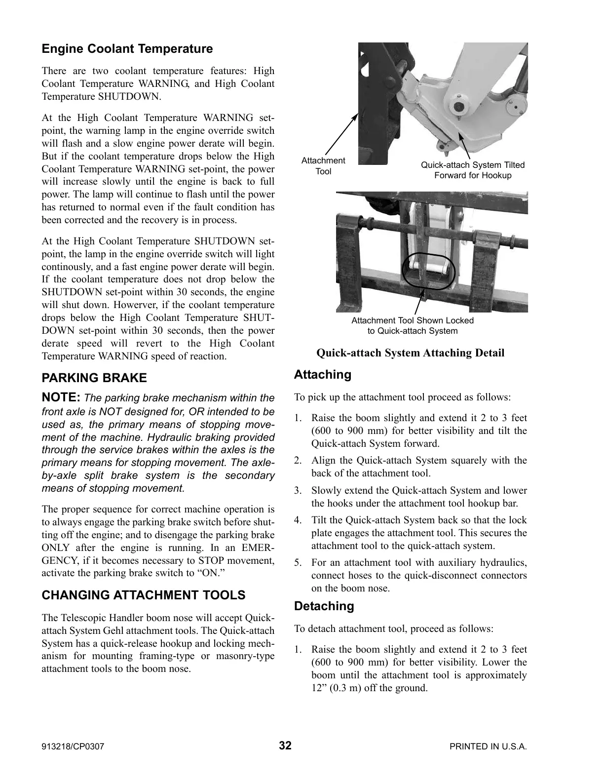
Attaching
To pick up the attachment tool proceed as follows:
1. Raise the boom slightly and extend it 2 to 3 feet
(600 to 900 mm) for better visibility and tilt the
Quick-attach System forward.
2. Align the Quick-attach System squarely with the
back of the attachment tool.
3. Slowly extend the Quick-attach System and lower
the hooks under the attachment tool hookup bar.
4. Tilt the Quick-attach System back so that the lock
plate engages the attachment tool. This secures the
attachment tool to the quick-attach system.
5. For an attachment tool with auxiliary hydraulics,
connect hoses to the quick-disconnect connectors
on the boom nose.
Detaching
To detach attachment tool, proceed as follows:
1. Raise the boom slightly and extend it 2 to 3 feet
(600 to 900 mm) for better visibility. Lower the
boom until the attachment tool is approximately
12” (0.3 m) off the ground.
Quick-attach System Attaching Detail
Attachment Tool Shown Locked
to Quick-attach System
Quick-attach System Tilted
Forward for Hookup
Attachment
Tool
 Loading...