7024US
7024US
7024US
7125TNC
M
YELLOW-BLUE (ON)
GREEN-BLUE (OFF)
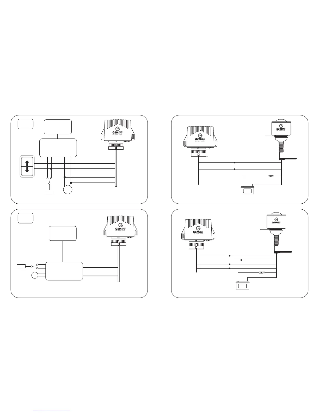
Diagram for codified receiver with single control switch free to rest.
E
ORIGINAL
RECEIVER
CENTRAL DOOR LOCKING
ORIGINAL UNIT
Earth
WHITE-L. BLUE
YELLOW-RED
Close
Open
Lock doors switch
7024US
YELLOW-BLUE (ON)
GREEN-BLUE (OFF)
F
ORIGINAL
RECEIVER
M
+/-
CENTRAL DOOR LOCKING
ORIGINAL UNIT
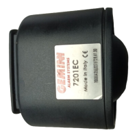
Connection 7024 unit with self-powered 7125TNC siren.
Connection 7024 unit with self-powered 7025 siren.
NOTE:
The Black wires have the identification
mark on the end. .
NOTE:
The Black wires have the identification
mark on the end. .
Clamp
BLACK nitialled RB
BLACK initialled RB
BLACK initialled MB
BLACK initialled MB
5A
PINK
BLUE
BLACK initialled L
BLACK initialled L
BLACK initialled R
BLACK initialled S
BLACK initialled S
BLACK initialled Z
Clamp
+
+
_
_
Battery
12VOLT
Battery
12VOLT
CODE
CODE
Diagram for codified receiver and central door locking unit supplied with connection
for the alarm system.
7025
15A
PINK
RED
BLUE
Fascetta
CLAMP
Do not connect