Page 19
GENERAL INFORMATION
Section 1.4
BRUSHED EXCITATION SYSTEM
windings and through the negative (-) slip ring and
brush on Wire 0.
The greater the current flow through the rotor wind-
ings, the more concentrated the lines of flux around
the rotor become. The more concentrated the lines
of flux around the rotor that cut across the stationary
stator windings, the greater the voltage that is induced
into the stator windings.
Initially, the AC power winding voltage sensed by the
regulator is low. The regulator reacts by increasing
the flow of excitation current to the rotor until volt-
age increases to a desired level. The regulator then
maintains the desired voltage. For example, if voltage
exceeds the desired level, the regulator will decrease
the flow of excitation current. Conversely, if voltage
drops below the desired level, the regulator responds
by increasing the flow of excitation current.
AC POWER WINDING OUTPUT:
A regulated voltage is induced into the stator AC
power windings. When electrical loads are connected
across the AC power windings to complete the circuit,
current can flow in the circuit.
CAPACITOR
STATOR
EXCITATION
WINDING
STATOR
POWER
WINDING
STATOR
POWER
WINDING
MAGNETIC
FIELD
MAGNETIC
FIELD
MLB = MAIN LINE
CIRCUIT BREAKER
ROTOR
TO LOAD
MLB
ENGINE -
DIRECT
DRIVE
AUTOMATIC
VOLTAGE
REGULATOR
+-
STATOR
EXCITATION
WINDING
STATOR
POWER
WINDING
STATOR
POWER
WINDING
MAGNETIC
FIELD
MAGNETIC
FIELD
SENSING
MLB = MAIN LINE
CIRCUIT BREAKER
ROTOR
TO LOAD
MLB
ENGINE -
DIRECT
DRIVE
120 VAC 120 VAC
240 VAC
120 VAC 120 VAC
240 VAC
A B
CAPACITIVE DISCHARGE DIRECT EXCITATION
Figure 2. 240 VAC Sensing Alternator
PART 1
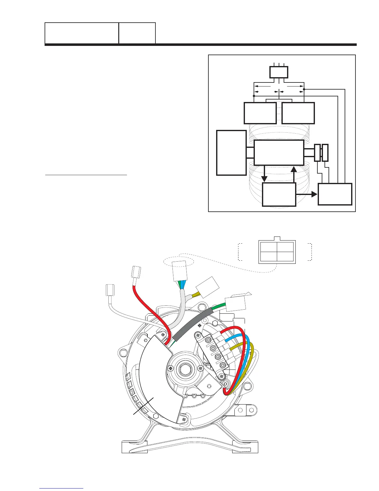
VOLTAGE REGULATOR
AVR SENSING
DPE
NOT USED
RED (R2 – 11)
BLUE (R1 – 22)
BLUE
BLUE
4 (+) RED
S15
2
S16
6
0 (-) WHITE
BROWN (L2 – 33)
WHITE (L1 – 44)
WHITE
GREEN
C1 FEMALE
C1 MALE
Figure 3. Alternator Configuration C
C