Page 14
PART 1
GENERAL INFORMATION
SECTION 1.2
MEASURING ELECTRICITY
Correct engine and Rotor speed is maintained by an
engine speed governor. For models rated 60 Hertz,
the governor is generally set to maintain a no-load fre-
quency of about 62 Hertz with a corresponding output
voltage of about 124 volts AC line-to-neutral. Engine
speed and frequency at no-load are set slightly high
to prevent excessive rpm and frequency droop under
heavy electrical loading.
MEASURING CURRENT
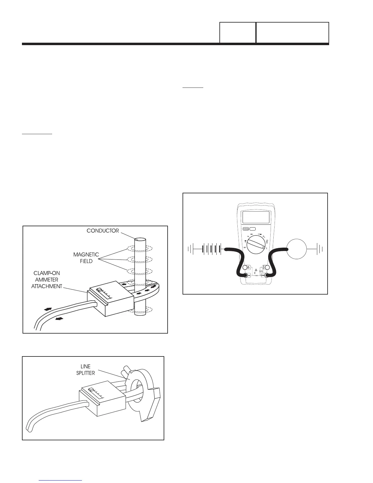
CLAMP-ON:
To read the current flow, in AMPERES, a clamp-on
ammeter may be used. This type of meter indicates
current flow through a conductor by measuring the
strength of the magnetic field around that conductor.
The meter consists essentially of a current transform-
er with a split core and a rectifier type instrument con-
nected to the secondary. The primary of the current
transformer is the conductor through which the current
to be measured flows. The split core allows the instru-
ment to be clamped around the conductor without
disconnecting it.
Current flowing through a conductor may be measured
safely and easily. A line-splitter can be used to measure
current in a cord without separating the conductors.
Figure 2. Clamp-On Ammeter
Figure 3. A Line-Splitter
NOTE: If the physical size of the conductor or amme-
ter capacity does not permit all lines to be measured
simultaneously, measure current flow in each indi-
vidual line. Then, add the individual readings.
IN-LINE:
Alternatively, to read the current flow in AMPERES, an
in-line ammeter may be used. Most Digital Volt Ohm
Meters (VOM) will have the capability to measure
amperes.
This usually requires the positive meter test lead to be
connected to the correct amperes plug, and the meter
to be set to the amperes position. Once the meter is
properly set up to measure amperes the circuit being
measured must be physically broken. The meter will
be in-line or in series with the component being mea-
sured.
In Figure 4 the control wire to a relay has been
removed. The meter is used to connect and supply
voltage to the relay to energize it and measure the
amperes going to it.
Figure 4. A VOM as an In-line meter
MEASURING RESISTANCE
The volt-ohm-milliammeter may be used to measure
the resistance in a circuit. Resistance values can be
very valuable when testing coils or windings, such as
the Stator and Rotor windings.
When testing Stator windings, keep in mind that the
resistance of these windings is very low. Some meters
are not capable of reading such a low resistance and
will simply read CONTINUITY.
If proper procedures are used, the following conditions
can be detected using a VOM:
• A“short-to-ground”conditioninany Statoror Rotor
winding.
•
Shorting together of any two parallel Stator windings.
•
Shorting together of any two isolated Stator windings.
• AnopenconditioninanyStatororRotorwinding.