EasyManua.ls Logo

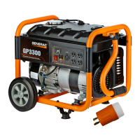
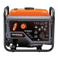
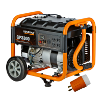
Generac Power Systems GP3250

Generac Power Systems GP3250
84 pages
To Next Page IconTo Next Page
Loading...
Diagnostic
RepaiR
Manual
PORTABLE GENERATORS
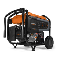
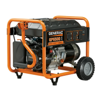
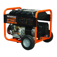
GP Series Portable Generators
MODELS:
GP1800
GP3250
GP5000
GP5500
GP6500
GP7000
GP8000
®

Table of Contents

Other manuals for Generac Power Systems GP3250

Questions and Answers:

Generac Power Systems GP3250 Specifications

General IconGeneral
Fuel TypeGasoline
Run Time at 50% Load10.5 hours
Noise Level68 dBA
Outlets4
Starting SystemRecoil
Running Watts3250 W
EngineGenerac OHV
Outlet Types(2) 120V 20A 5-20R
Wheel KitNo

Summary

Safety Information

Safety Alerts and Precautions

Details on DANGER! and CAUTION! blocks, emphasizing hazard awareness and accident prevention.

Notice to Users of this Manual

Information for mechanics on manual usage, assumptions about training, and safety responsibilities.

Part 1 General Information

Section 1.1 Generator Fundamentals

Explains the basic principles of magnetism, electromagnetism, and AC generation.

Section 1.2 Measuring Electricity

Covers the use of meters (VOM) and electrical units for measurements.

Section 1.3 Brushless, Capacitor Excitation System

Details the components and operation of the brushless, capacitor-based excitation system.

Section 1.4 Brushed Excitation System

Describes the components and operation of the brushed excitation system.

Section 1.5 Testing, Cleaning and Drying

Procedures for testing insulation resistance, cleaning, and drying generator components.

Part 2 AC Generators

Section 2.1 Brushless Capacitor Troubleshooting Flowcharts

Flowcharts to diagnose issues with brushless capacitor type alternators.

Section 2.2 Brushed Excitation Troubleshooting Flowcharts

Flowcharts to diagnose issues with brushed excitation alternators.

Section 2.3 AC Diagnostic Tests

Specific tests to check various AC generator components and functions.

Part 3 Engine Troubleshooting

Section 3.1 389206163 cc Troubleshooting Flowcharts

Troubleshooting guides for 389cc, 206cc, and 163cc engines.

Section 3.2 410 cc Troubleshooting Flowcharts

Troubleshooting guides for 410cc engines.

Section 3.3 Diagnostic Tests

Specific diagnostic tests for engine starting, running, and component checks.

Part 4 Disassembly

Section 4.1 Major Disassembly

Provides exploded views and basic disassembly steps for generator models.

Part 5 Electrical Data

Electrical Schematic, GP1850

Electrical schematic diagram for the GP1850 model.

Electrical Schematic, GP3250

Electrical schematic diagram for the GP3250 model.

Electrical Schematic, GP500055006500

Electrical schematic diagrams for GP5000, GP5500, and GP6500 models.

Wiring Diagram, GP500055006500

Wiring diagram for GP5000, GP5500, and GP6500 models.

Electrical Schematic, GP7000 E8000 E

Electrical schematic diagram for GP7000E and GP8000E models.

Wiring Diagram, GP7000 E8000 E

Wiring diagram for GP7000E and GP8000E models.

Electrical Formulas

Formulas used for electrical calculations related to generators.

Related product manuals