Generac
®
Power Systems, Inc. 5
1.8 ADJUSTING THE LOAD BLOCK
When the natural gas system is being used, the load
block is fitted with an adjustment screw that has
been calibrated to provide maximum power.
However, because of variations in the Btu content of
natural gas across the country, it may be necessary to
readjust the load block.
• Connect a frequency meter to the output of the gen-
erator.
• Start the unit and apply full load according to the
following chart:
• Allow the unit to stabilize; then, turn the adjust-
ment screw slowly clockwise or counterclockwise
and watch the frequency.
• When the highest frequency is reached, turn the
adjustment screw counterclockwise 1/4 turn.
• The fuel system is now set.
• For LP gas operations, the hose and blanking plug
must be reconfigured as shown in Figure 1.4, (Page
7) of the owner’s manual. The unit is set to provide
maximum power using LP gas.
Do not make any unnecessary adjustments.
Factory settings are correct for most applica-
tions. However, when making adjustments, be
careful to avoid overspeeding the engine.
1.9 ENGINE GOVERNOR ADJUSTMENT
If both AC frequency and voltage are correspondingly
high or low, adjust the engine governor as follows:
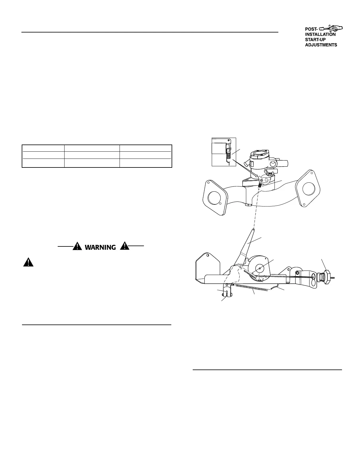
1.9.1 8 KW AND 10 KW UNITS
1. Loosen the governor clamp bolt (Figure 1.3).
2. Push the spring end of the governor lever clock-
wise to the wide open throttle position of
the lever.
• Hold the governor lever at wide open throttle and,
with a screwdriver, rotate the governor shaft fully
clockwise.
• Before tightening, verify that the governor lever is
pushed all the way onto the governor shaft.
• While holding the governor shaft fully clockwise
and the governor lever at wide open throttle,
tighten the governor clamp bolt to 130 inch-
pounds (8 N-m).
3. Start the engine; let it stabilize and warm up at
no-load.
4. Turn the speed adjust nut to obtain a frequency
reading of 62 Hertz.
5. When frequency is correct at no-load, check the
AC voltage reading. If voltage is incorrect, the volt-
age regulator may require adjustment.
Figure 1.3–8kWand10kW
Engine Governor Adjustment
NOTE:
If the engine continues to run fast, use a pair of
pliers to bend the bend tab clockwise to release
tension on the lower governor spring.
1.9.2 ADDITIONAL CORROSION PROTECTION
Periodically spray all engine linkage parts and brack-
ets with corrosion inhibiting spray such as WD-40 or
a comparable product.
◆
 Loading...